



Only cars with 16-valve engines
A special tool is required to screw in (reinstall) the pistons. If you do not have a special tool, you can make one yourself with a certain amount of skill, otherwise contact a service station.
Removal
Mark the position of the wheel disk on the hub of the knee with paint. This ensures that the balanced wheel can be reinstalled in its original place.
Raise the rear of the car, see item 29.
Remove the wheel.
Caution: Do not swap the pads from the outer to the inner side and vice versa, or from the right to the left wheel and vice versa. Swapping the pads may result in uneven braking. Always replace all pads on one axle at the same time. If you need to reinstall the pads, mark the pads before removing them.
Release the handbrake.
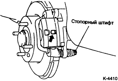
Unscrew the locking pin, tilt the brake caliper upwards and secure it to the car with wire. Make sure that the brake hose is not stretched.
Caution: The locking pin is coated with a special lubricant. Do not remove the lubricant under any circumstances. Make sure that no dirt gets in there.
Pull the piston body upward and attach it to the body with wire.
Caution: Do not remove the brake hose, otherwise you will have to bleed the brake system.
Remove the brake pads with spacer springs, spacer washers and anti-squeak linings.
Installation
Caution: When the brake pads are removed, do not press the brake pedal, otherwise the piston will be pushed out of the housing. If the piston comes out due to an oversight, contact a MITSUBISHI service station to install the piston.
Clean the guide surfaces and the pad seats with a soft metal brush or wash with a cloth soaked in alcohol. Do not use any solvents containing mineral oils or tools with sharp edges.
Before installing the pads, check with your fingers for grooves on the brake disc. If there are grooves or scratches, replace the brake disc.
Measure the thickness of the brake disc, see paragraph 18.3.
Make sure there are no tears or cracks in the dust boot and seals in the caliper. Replace a damaged dust boot immediately, as penetrating dirt quickly leads to depressurization of the brake caliper. To do this, the caliper must be removed and disassembled (work in a workshop).
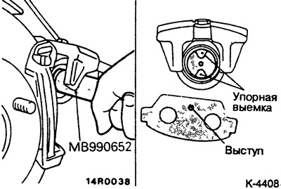
Slowly screw the brake piston clockwise until it stops in the brake caliper using the special tool MB-990652. The caliper does not need to be removed for this.
Caution: The brake piston must be screwed in. If it is simply pressed in, the automatic handbrake setting device will be damaged.
To turn the piston, a special tool is inserted into the stop recesses. If you do not have a special device, you can make one yourself with a certain amount of skill, otherwise contact a service station.
Note: When turning the piston, the brake fluid is squeezed into the reservoir. Observe the level of brake fluid in the reservoir, it is possible to suck out the brake fluid with a suction device.
When sucking, use a plastic bottle that is only for brake fluid. Do not use beverage bottles! Brake fluid is poisonous and should never be sucked out through a hose by mouth. Use suction devices. After replacing the pads, the brake fluid level in the reservoir should not exceed the MAX mark, since the fluid expands when heated. Leaking brake fluid flows onto the master cylinder, destroys the paint and causes corrosion.
The article is reprinted from a web resource [MitsubishiMan.ru]
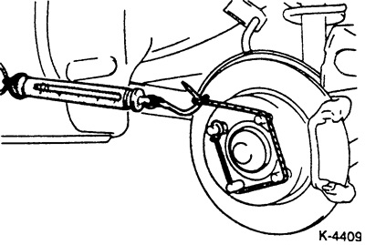
Measure the wheel hub breakaway torque as shown in the figure and record the measured value. To do this, tighten the wheel nuts to secure the brake disc to the wheel hub.
To prevent disc brakes from squeaking, coat the backs of the brake pads and anti-squeal linings with a thin layer of lubricant (e.g. Plastilube, Tunap VC 582/S, Chevron SRJ/2, Liqui Moly LM-36 or LM-508-ASC, brake paste SAE J310 NLGI No.1). Under no circumstances should the lubricant come into contact with the working surface of the brake pad or the brake disc. If it does come into contact with the lubricant, wipe it off immediately and clean the surface with alcohol. Apply the paste in such a thin layer that when the brake pad is pressed down during braking, it does not protrude beyond the edge.
Note: Paste is included in some repair kits.
Slide both brake pads with new anti-squeal linings into the retaining springs in the caliper bracket.
Tilt the piston body downwards and insert and secure the locking pin.
Start the engine and press and hold the brake pedal for about 5 seconds. This will cause the brake pads to engage. Switch off the engine and rotate the wheel hub 10 revolutions forward. Then measure the wheel hub breakaway torque, see Fig. K-4405. Compare the measured value with the breakaway torque measured with the old brake pads. If the difference exceeds the required value, disassemble and repair the brake caliper (workshop work). Required value: 70 N (7.0 kg) or less.
Give away the wheel nuts.
Position the wheels according to the markings, screw in the wheel nuts. Lower the car and tighten the nuts crosswise. Tightening force see item 19.4.
Start the engine and press the brake pedal hard 6-7 times until strong resistance appears. After that, check the handbrake lever stroke and adjust if necessary.
Check the fluid level in the tank and, if necessary, top up to the MAX mark.
Adjust the handbrake, see item 18.15.
Carefully break in the new brake pads by applying light pressure to the brake pedal several times, from 80 km/h to 40 km/h. Allow the brakes to cool between brakings.
Attention: Avoid full braking during the first 200 km.