



Warning: Replacement of disc brake pads must be performed on both front or rear wheels at the same time: never replace pads on only one wheel. In addition, dust generated in the brake system may contain asbestos, which is harmful to your health. Never blow off dust with compressed air or inhale it. Wear a cloth mask when working on the brakes. Do not use kerosene-based solvents to clean the brake system. Use only special brake system cleaners or alcohol.
Note: When servicing disc brakes, use only high quality pads of recognized manufacturer brands.
1. Remove the cap from the brake fluid reservoir (see Chapter 1) and pump out about 2/3 of the fluid from the reservoir. Otherwise, the fluid may splash out of the reservoir when pressing the pistons into the channels.
2. Apply the handbrake. Loosen the wheel nuts, lift the car and secure it on supports. Block the wheels that are on the ground.
3. Remove the wheels. Work on only one brake assembly at a time, using another brake assembly for comparison if necessary.
4. Carefully inspect the brake disc as described in section 5. If mechanical treatment is required, remove the brake disc as described in this section. In addition, the brake pads can also be removed from the brake mechanism.
5. The procedure for replacing the pads varies depending on the type of brake mechanism (one-piece or consisting of two parts - housing and caliper).
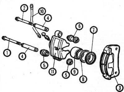
3.5a. Front brake mechanism - PFS15 (Mirage models). 1. Bolt, 2. Bolt, 3. Brake caliper (with pads, holders and gaskets), 4. Bushing, 5. Bushing boot, 6. Bushing, 7. Dust cover, 8. Piston seal, 9. Piston, 10. Brake hose, 11. Brake housing
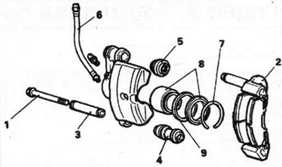
3.5b. Front brake mechanism - AD54 shown, AD60 - similar (non-turbo Cordla/Tredla/Galant models). 1. Locking pin, 2. Brake caliper (with pads, holders and linings), 3. Bushing, 4. Locking pin boot, 5. Guide pin boot, 6. Brake hose, 7. Boot ring, 8. Piston with boot, 9. Piston seal
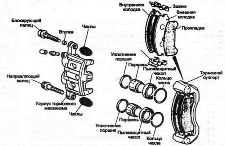
3.5 sec. Front brake mechanism - Galant turbo models from 1991 inclusive
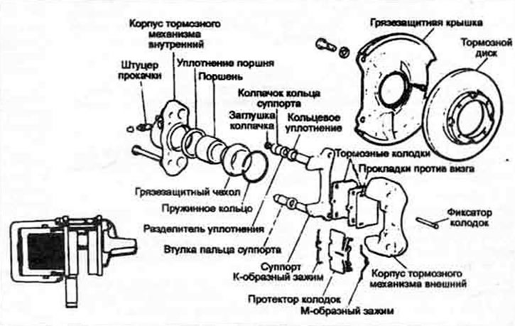
3.5d. Front brake mechanism - Sumitomo (Precis models)
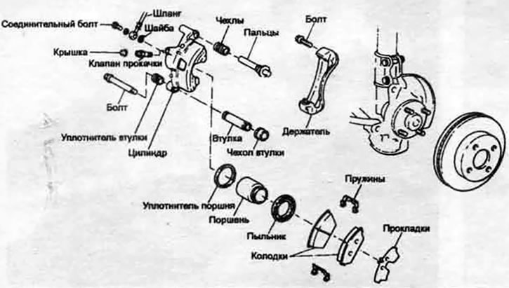
3.5e. Front brake mechanism - Tokico (Precis models)
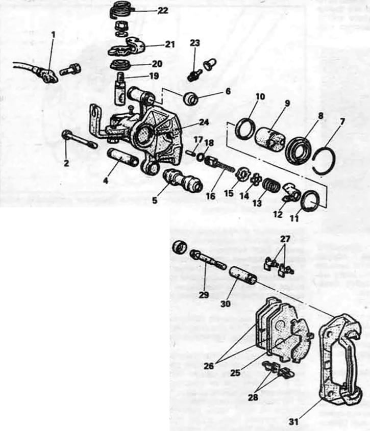
3.5f. Rear disc brake - AD54 (Galant models). 1. Brake hose, 2. Locking pin, 3. Not used, 4. Locking pin sleeve, 5. Locking pin boot, 6. Guide pin boot, 7. Boot ring, 8. Dust boot, 9. Piston, 10. Piston seal, 11. Expander ring, 12. Spring housing, 13. Return spring, 14. Spring washer, 15. Stopper, 16. Automatic adjuster shaft, 17. Connecting link, 18. O-ring, 19. Axle lever, 20. Lever boot, 21. Parking brake lever, 22. Return spring, 23. Bleed nipple, 24. Brake mechanism housing. 25. Outer adjusting shim, 26. Pads, 27. Spring clip, 28. Spring clip B, 29. Guide pin, 30. Guide pin sleeve, 31. Caliper
Sumitomo brake mechanism (Precis models)
6. Replace the brake pads for this type of brake mechanism in accordance with illustrations 3.6a - 3.6k. Follow the replacement order, carefully read the captions to the illustrations. Then proceed to step 13.
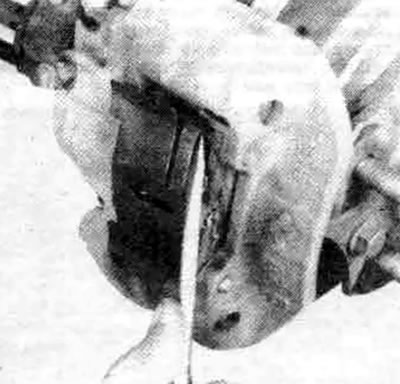
3.6a. Remove the shoe holder from the retaining pins
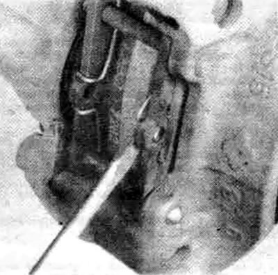
3.6s. Remove the central part of the clamp from the outer brake shoe...
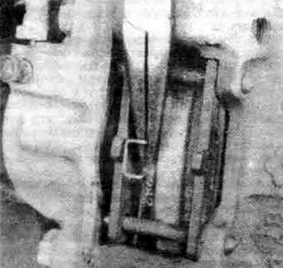
3.6e. Using pliers, remove the spring from the inner brake shoe and from under the retaining pins
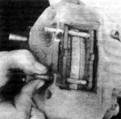
3.6f. Pull out both locking pins
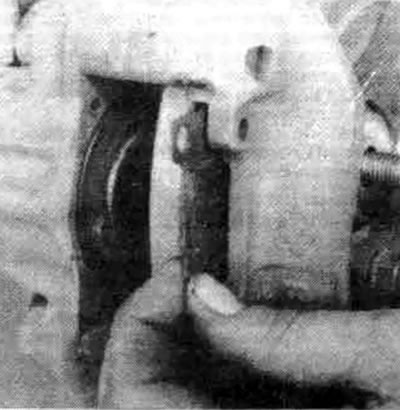
3.6l. If the anti-squeal pads are not left on the pads, remove them from the brake mechanism
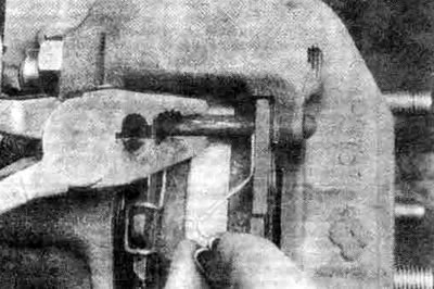
3.6k. Install new pads and clamps, referring to the unit on the other side of the car if necessary. When installing a clamp, fit one end into the hole in one retaining pin, then turn the other pin so that its hole is correctly angled to fit the other end of the clamp, taking the center of the clamp into the hole in the brake shoe
Braking mechanisms of other designs
7. Use a C-clamp to compress the piston in the brake mechanism.
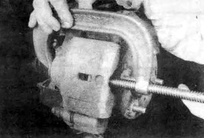
3.7. Use a clamp to compress the piston and release the brake pads
8. Remove the brake retaining pin or lower mounting bolt.
9. Turn the brake mechanism upward so that the brake pads can be removed, then fix the brake mechanism in this position with a piece of wire.
10. Remove the brake pads from the caliper. Remove the spring clips (if any) from both ends of the caliper, noting their location. Inspect each clip, and replace them if they are deformed.
11. Use a wooden tool, such as a hammer handle, to take the brake piston into the bore. This will create space for installing the new pads.
12. Apply anti-seize compound to the brake pad calipers according to the instructions on the label.
13. Position the spring clips on the caliper (if equipped). Attach the anti-squeal shims to the outer pad (see illustrations 3.5a through 3.5e), then install the pads.
14. Rotate the brake housing downwards, position it over the shoes, then install the retaining pin or lower mounting bolt, tightening it to the torque specified in specifications of this Chapter.
All models
15. After replacing the pads, press the brake pedal hard several times to ensure that the pads come into contact with the disc. The pedal should be at a normal height from the floor and feel firm.
16. Check the fluid level in the master cylinder reservoir, top up if necessary (see Chapter 1). Make sure there are no fluid leaks, check the operation of the brakes.