



Contents: Removal ⤓ Sumitomo brake mechanism ⤓ Braking mechanisms of other designs ⤓ Bulkhead ⤓ Installation ⤓
Warning: Dust generated in the brake system may contain asbestos. Never blow off dust with compressed air. Wear a cloth mask when working on the brakes. Do not use kerosene-based solvents to clean the brake system. Use only special brake system cleaners or alcohol.
Note: If an overhaul is required (usually indicated by fluid leaks), study all possible options before starting work. If you decide to overhaul the brake mechanism yourself, purchase a repair kit of parts. Overhaul both brake mechanisms at once - overhauling one of them is unacceptable.
Note: For brake mechanism identification, see illustrations 3.5a through 3.5e.
Removal
1. Remove the cap from the brake fluid reservoir and pump out about 2/3 of the fluid, do not use this fluid in the future. Remember that brake fluid corrodes the paintwork of the car, try not to spill it.
Note: The rest of the removal procedure depends on the type of brake mechanism (one-piece or two-piece). To determine the type of brake mechanism you have, look at the shoe holder. If the holder matches the one shown in Illustration 3.6a, your vehicle has a one-piece brake mechanism. Otherwise, your brake mechanism consists of two parts.
2. Apply the parking brake. Loosen the wheel nuts, raise the front of the car and place it on supports. Remove the front wheels.
Sumitomo brake mechanism
3. Remove the brake pads from the brake mechanism as described in section 3.
4. Loosen the hose nipple on the frame bracket, then remove the hose retaining clamp (see section 10). You can now unscrew the brake hose from the brake mechanism. Plug the end of the hose to prevent fluid loss.
5. If you decide to disassemble the brake mechanism, loosen the two bolts that hold the two parts of the brake mechanism together. Unscrew the two mounting bolts and remove the brake mechanism from the car.
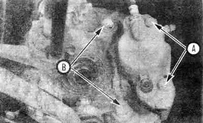
4.5 If the Sumitomo brake mechanism is removed for overhaul, loosen the bolts that hold the inner and outer parts of the brake mechanism housing (A), these bolts are very tight, so it is easier to unscrew them before removing the brake mechanism. Then unscrew the brake mechanism mounting bolts (B) and remove the brake mechanism from the car
Braking mechanisms of other designs
6. Disconnect the brake line from the brake mechanism by unscrewing the inlet fitting bolt. Plug the end of the line to prevent fluid loss.
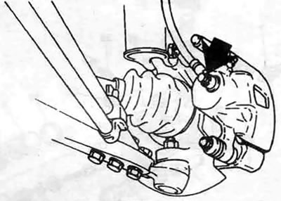
4.6. Unscrew the inlet fitting bolt (shown by the arrow), if present on your model
7. Loosen the brake caliper mounting bolts or, on some models, the retaining pin, rotate the brake caliper upwards so that it clears the brake disc, then lift it off the upper pin. The brake pads may remain on the caliper.
Bulkhead
8. Clean the outer surface of the brake mechanism with a special cleaner or alcohol.
Warning: Do not use gasoline, kerosene or solvents based on them.
9. If you are rebuilding a Sumitomo type brake mechanism, unscrew the two bolts holding the two halves of the brake mechanism housing together and separate the housing. Now you can remove the caliper.
10. Depending on the design of the brake mechanism, the piston can be removed in one of two ways:
- a) For Sumitomo type brakes, place the brake mechanism on the table, the part of the brake mechanism where the piston is located should be at the bottom, use compressed air to remove the piston from the brake mechanism.
- b) On other brake designs, place a block of wood or rag into the brake as a cushion, then apply compressed air to the inlet port to force the piston out.
When using any of the methods, the air pressure should not exceed that required to remove the piston. If the piston is pulled out of the channel with great force, it may be damaged.
Warning: Do not place your hands against the piston while it is being blown out with compressed air, as this may cause serious injury.
Note: On 1991 and later Galant Turbo models, only one piston will come out. Place this piston into the bore without forcing it, secure it, then use compressed air again to pull out the second piston.
11. Remove the dust cover. First remove the wire clip (if any), then remove the cover.
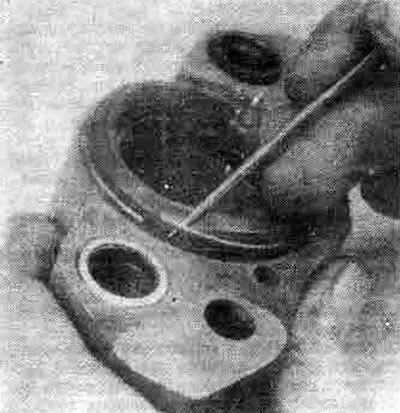
4.11 Remove the wire retaining ring from the dust cover, then remove the cover
12. Using a wooden or plastic tool, remove the piston seal from the groove in the brake channel. A metal tool may damage the brake channel.
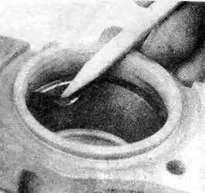
4.12. To avoid damaging the brake channel or the groove for the seal, remove the piston seal using a plastic or wooden tool (a pencil works well)
13. Unscrew the bleed screw. On Sumitomo brakes, remove the caliper pin bushing from the brake housing. On other models, remove the pin boot, sleeve boots and sleeve, if applicable. Rubber parts are not to be used further.
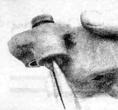
4.13. To remove the support disc pin bushing, grip it with needle-nose pliers, turn it and pull it out through the brake housing
14. Wash the remaining parts with a special cleaner or alcohol, then dry with compressed air (the air must pass through the filter and be dry).
15. Carefully inspect the piston for nicks and burrs. If the surface is damaged, the parts must be replaced.
16. Check the brake bore for nicks, burrs and corrosion. Minor surface damage and corrosion can be removed with sandpaper. If the mounting bolts are corroded or damaged, replace them.
17. Wet the piston bore with clean brake fluid. Lubricate the new piston seal with the silicone grease from the repair kit (or clean brake fluid if silicone grease is not available), then place the seal into the brake bore groove.
18. If the brake mechanism design requires the use of a retaining ring on the dust boot, wet the piston with clean brake fluid, place the piston in the brake mechanism, then press it into the bore with your fingers. Lubricate the piston groove with silicone grease from the repair kit, then pull the dust boot over the top of the piston and install the retaining ring.
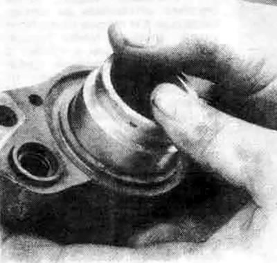
4.18 a. On Sumitomo brakes, install the plunger in the brake channel, then push it inwards so that the dust cap groove is sunk flush with the surface of the brake mechanism
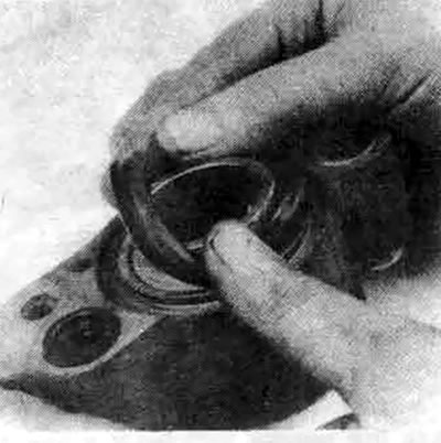
4.18b. Pull the dust cover over the top of the piston,...
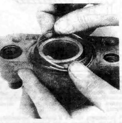
4.18s....then install the retaining ring
19. On brake mechanisms of other designs, lubricate the piston and the edges of the piston boot with silicone grease from the repair kit, then pull the dust boot onto the lower (closed) end of the piston. Lower the piston with the boot into the brake mechanism channel and seal the corrugated part of the dust boot into its groove in the channel. After sealing the boot along the entire perimeter, you can press the piston into the channel.
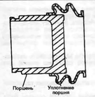
4.19a. On models without a retaining ring on the boot, install the boot on the bottom of the piston...
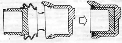
4.19b....then seal the corrugated part of the boot into the upper groove of the brake mechanism channel and insert the piston into the channel
20. On Sumitomo type brakes, apply a coat of silicone grease to the caliper pins, then install the disc by sliding the pins through the inner half of the brake housing. Place the housing halves together, install the bolts and tighten them to the torque specified in specifications of this Chapter.
21. On other models, lubricate the bushing, pin channel and boots with silicone grease, then install them in the correct order into the brake mechanism.
[Original material on the website mitsubishiman.ru]
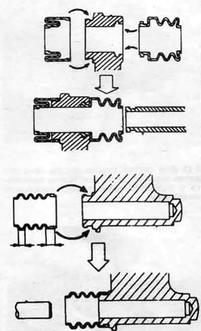
4.21. On brake mechanisms of other models, apply silicone grease to the rubbing surfaces of the bushing and pin, into the brake mechanism channel and to the edges of the rubber boots on the clutch side, install the rubber boots first, then the bushing
Installation
22. On Sumitomo type brakes, position the brake assembly over the disc, aligning the threaded holes in the caliper with the holes in the steering knuckle. Install the mounting bolts, tightening them to the torque specified in the specifications in this Chapter. The brake hose and pads can now be installed.
23. On other models, make sure the brake pads are in place, then position the brake assembly over the upper mounting pin (on applicable models). Rotate the brake assembly downwards so that it is over the pads and disc, then install the mounting bolts (or retaining pin), tightening them to the specifications in this Chapter. Attach the brake hose using new copper washers on each side of the inlet fitting bolt. Tighten the inlet fitting bolt to the torque specified in this Chapter.
24. Bleed the brakes as described in section 11.
25. Install the wheels and lower the vehicle to the ground. Tighten the wheel nuts to the torque specified in chapter 1 specifications.
26. Press the brake pedal hard several times to ensure that the pads come into contact with the disc.
27. Inspect the brake mechanism for leaks and check the operation of the brakes.