



Note: If your vehicle is equipped with anti-lock braking system (ABS), have it overhauled by your dealer.
Removal
1. The brake master cylinder is located in the engine compartment and is attached to the brake booster.
2. Using a syringe, remove as much liquid as possible from the tank.
3. Place rags around the pipe fittings and prepare plugs to seal the ends of the pipe after disconnecting them.
Caution: Brake fluid will damage the paintwork of your vehicle. Cover all body parts and avoid spilling brake fluid while working.
4. Loosen the pipe nuts at the ends of the pipes. at the joints with the brake master cylinder. Use a special wrench to prevent the flat edges of the nuts from rounding.
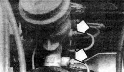
8.4. Unscrew the pipe fittings (shown by arrows) using a spanner
5. Slightly move the lines away from the master cylinder and plug the ends to prevent dirt from getting in. If the master cylinder has a removable reservoir, disconnect the hose from the master cylinder and plug it.
6. Disconnect the electrical connector from the brake master cylinder, then unscrew the three nuts that secure the brake master cylinder to the booster. Remove the brake master cylinder from the studs and remove it from the engine compartment. Be careful not to spill any brake fluid.
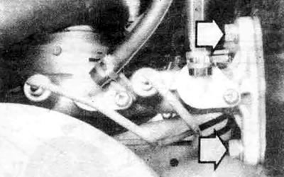
8.6. Disconnect the electrical connectors, then unscrew the nuts securing the brake master cylinder (shown by arrows);
Note: Some models use removable tanks.
Bulkhead
7. Before you begin overhauling the master brake cylinder, purchase the appropriate repair kit containing the parts needed for replacement, as well as instructions, specifically for your vehicle model.
8. Inspect the tank rubber bushings for leaks at the base of the tank. Remove the tank.
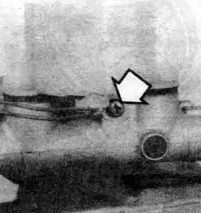
8.8a. Unscrew the tank mounting screw (shown by arrows)...
9. Secure the cylinder in a vice, then use a punch or Phillips screwdriver to push the pistons so that their bottom ends are level with the other end of the master cylinder. Lock the pistons in this position and unscrew the locking bolt located on the side of the master cylinder.
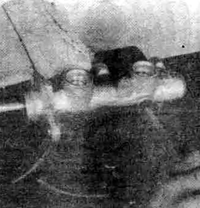
8.9. Press the pistons fully in and then loosen the lock screw
10. Carefully remove the expansion ring at the end of the master cylinder
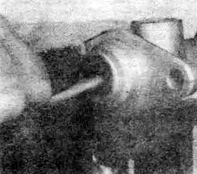
8.10 Press the pistons inward, then remove the compression ring
11. Now you can remove the internal parts from the channel. Remember the order of the parts.
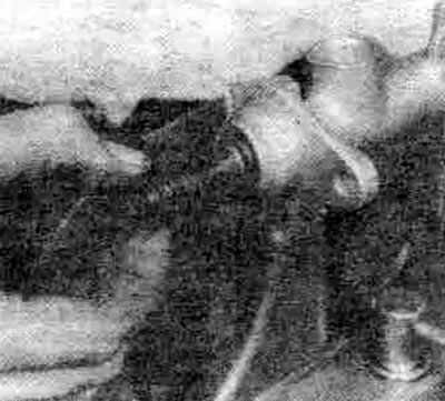
8.11a. Remove the first piston from the master cylinder channel
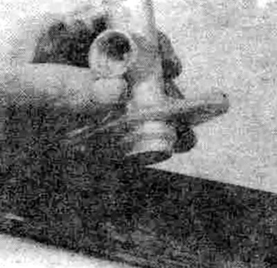
8.11b. To remove the second piston, tap the master cylinder several times on a wooden block
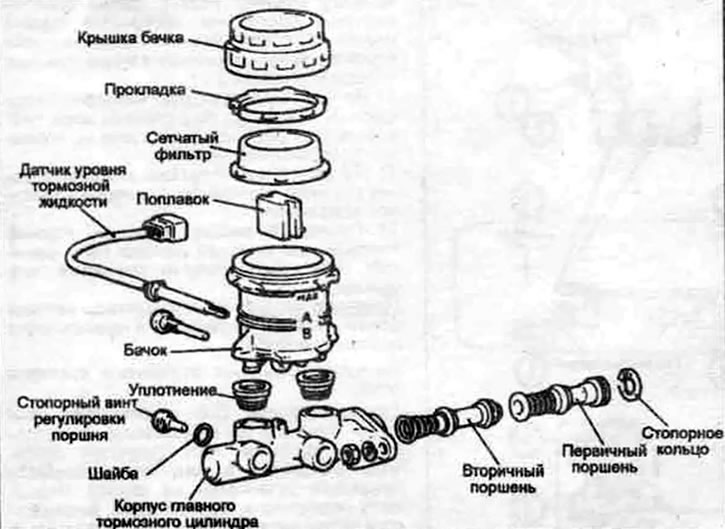
8.11c. Exploded view of the brake master cylinder (typical)
Note: Pay particular attention to the order of the two springs, as they have different tensions.
12. Carefully inspect the brake master cylinder bore. If there are deep scratches or other damage, the brake master cylinder must be replaced.
13. Replace all parts included in the repair kit following the instructions provided. Before reusing old parts, wash them in clean brake fluid, brake cleaner or alcohol. Do not use kerosene-based solvents. Wet all parts with clean brake fluid during assembly.
14. Sink the assembled unit into the channel, then install the locking bolt. Be sure to install a new gasket on the locking screw.
15. Install the new expansion ring, making sure it is correctly positioned in the groove.
16. Before installing the master brake cylinder, it must be bled. Since during the bleeding process it is necessary to simultaneously apply pressure to the piston and monitor the flow coming out of the outlet holes of the brake pipes, it is recommended to fix the master brake cylinder in a vice, grasping it with jaws by the mounting flange. The brake cylinder body is made of aluminum, so handle it with care.
17. Install the threaded plugs into the outlet holes of the brake pipes and screw them tightly so that no air passes through them and, at the same time, they can be easily unscrewed.
18. Fill the reservoir with the recommended type of brake fluid (see Chapter 1).
19. Unscrew one plug and push the piston into the master cylinder bore to bleed the air. You can use a large Phillips screwdriver to do this.
20. To prevent air from getting back into the master cylinder, the plug must be screwed tightly again before releasing the piston.
21. Repeat the procedure until only brake fluid flows out of the brake pipe outlet of the brake master cylinder. Once this is achieved, repeat the operation on the other outlet. Maintain the brake fluid level in the reservoir, otherwise air may enter the system.
22. Since the bleeding procedure does not require high pressure, another method can be used instead of removing and installing the plugs. Before pressing the piston, remove the plug as described in step 19. However, before releasing the piston, instead of installing the plug, simply plug the hole with your finger. Wait a few seconds for the fluid from the reservoir to flow into the cylinder bore, then press the piston again, remove your finger, allowing the fluid to flow out. Each time, plug the hole with your finger before releasing the piston. After completing the bleeding procedure for a given hole, replace the plug, screw it tightly and move on to the next hole.
Installation
23. Install the brake master cylinder onto the brake booster studs and tighten the mounting nuts.
24. Screw the brake pipe fittings to the master cylinder and the junction block. Since the master cylinder nuts are not tightened, it can move slightly, which makes it easier to make the connections. When tightening the connections, be careful not to strip the threads.
25. Fully tighten the master cylinder mounting nuts and pipe connections.
26. Fill the brake master cylinder reservoir with fluid, then bleed the brake master cylinder (if it was not bled after overhaul) and the entire brake system as described in section 11. When bleeding the cylinder after installation, have an assistant press the brake pedal several times and hold it near the floor. Loosen the coupling nut to allow air and fluid to flow out. Repeat this procedure on all couplings until the fluid flowing out is free of air bubbles. Before starting normal operation of the vehicle, carefully check the brake operation.