
English Русский
Български
Беларускі
Український
Српски
Hrvatski
Română
Polski
Slovenský
Magyar
Articles Bookmark Contacts Sitemap   
Company Audi Company Ford Company Hyundai Company Kia Company Mazda Company Mercedes-Benz Company Nissan
MitsubishiMan.ru


Home Colt Lancer Galant L200 Outlander Pajero Others
Galant 6 and 7 (1987-1998) Galant 5 (1983-1989, petrol)

Brake booster — inspection, removal and installation (Mitsubishi Galant 5)

  • Home
  • Galant
  • 5 (1983-1989, petrol)
  • Chassis and running gear
  • Brake system
  • Brake booster — inspection, removal and installation
0
Contents: Checking the work ⤓ Air tightness test ⤓ Removal ⤓ Installation ⤓

Checking the work


1. With the engine off, press the brake pedal several times. Make sure that the pedal travel does not change.

2. Press the pedal and start the engine. If the pedal moves down slowly, the brake booster is working properly.

Air tightness test


3. Run the engine for one or two minutes, then turn it off. Slowly press the brake pedal several times. If the pedal drops lower the first time you press it, and gradually rises the second and third time you press it, the booster is airtight.

[Article reprinted from the website MitsubishiMan]

4. With the engine running, press the pedal, turn off the engine. without releasing the pedal. If after pressing the pedal for 30 seconds, the power reserve has not changed, the booster is airtight.

Removal


5. To disassemble the brake booster, you need special tools that are not available in auto parts stores. The brake booster is a complex device that has a decisive influence on the characteristics of the brakes, so it is better to replace the brake booster with a new or refurbished one.

6. In order to remove the brake booster, you must first remove the brake master cylinder as described in section 8. Pull the pressure limiter and bracket forward, being careful not to bend the pipes.

7. Locate the pushrod fork that connects the booster to the brake pedal. The fork is accessible from inside the vehicle in front of the driver's seat.
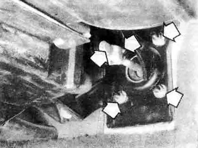


12.7 Remove the fork pin, then unscrew the booster mounting nuts (shown with arrows) (Precis model shown, others are similar)


8. Remove the fork pin cotter pin with pliers, then remove the pin.

9. Hold the fork with pliers and unscrew the fork lock nut with a wrench. Now you can remove the fork.

10. Disconnect the hose that goes from the engine to the booster. Be careful not to damage the hose when disconnecting it from the booster.

11. Unscrew and remove the four nuts and washers securing the amplifier to the bulkhead. You may need the lamp for this, as they are located under the front panel.

12. Slide the booster straight away from the bulkhead until it clears the studs, then remove the booster, brackets and spacers from the engine compartment.

Installation


13. The installation procedure is basically the reverse order. Firmly tighten the fork lock nut and the booster mounting nuts to the torque specified in the specifications in this chapter.

14. If you have replaced the booster, you need to check the clearance between the master cylinder piston and the booster plunger. Using a bore micrometer, measure the distance from the socket (concave section) on the master cylinder to the master cylinder mounting flange. Then measure the distance from the end of the booster plunger to the booster mounting surface, including the gasket. Subtract one measurement from the other to get the clearance. If the clearance is outside the acceptable range, adjust by turning the screw on the end of the booster plunger.
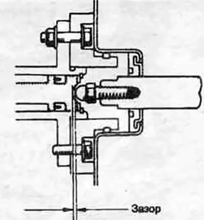


12.14a. The clearance between the booster pushrod and the piston of the brake master cylinder must comply with the specification. If there is no clearance, the brakes may seize; if the gap is too large, the pedal stroke will increase excessively
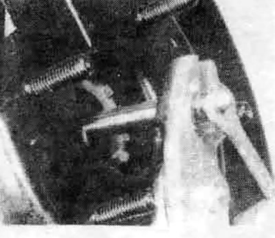


12.14b. To adjust the booster tappet, grip the toothed portion of the tappet with pliers, then turn the adjusting screw in the desired direction to set the desired clearance


15. After final installation of the master brake cylinder, brake pipes and hoses, it is necessary to bleed the system (see section 11).
This article is available at: russian, bulgarian, belarusian, ukrainian, serbian, croatian, romanian, polish, slovak, hungarian
This article was reviewed by: Vladimir Glazunov
Share with friends:
◀ Previous
Galant 5: Brake system
Next ▶

Hydraulic brake system — bleeding
Brake Hoses and Tubes — Inspection and Replacement
Brake force regulator — removal and installation
Master Brake Cylinder — Removal, Overhaul and Installation
Wheel brake cylinder — removal, overhaul and installation
Parking brake — adjustment
Parking Brake Cables — Replacement
Similar materials for other Mitsubishi models

➤ Brake booster valve Mitsubishi Colt 5 (1995-2003, petrol)
➤ Checking the operation of the brake booster Mitsubishi Lancer 9 (2000-2007, petrol)
➤ Checking the brake booster Mitsubishi L200 4 (2005-2014, diesel)
➤ Removal and installation the brake master cylinder and… Mitsubishi Outlander 1 (2003-2008)
➤ Vacuum brake booster — removal, inspection and installation Mitsubishi Pajero 1 and 2 (1982-1999)
➤ Checking the performance of the brake booster Mitsubishi Carisma (1995-2004)
Link in different formats to this article
Comments and feedback from visitors
No comments yet


Add up two numbers 49 + 44


Galant 6 and 7 (1987-1998) 
  • General information
  • Introduction to guide
  • User manual
  • Driving and operation
  • Maintenance
  • Power unit
  • Dismantling the engine
  • Engine overhaul
  • Cooling and heating
  • Power and exhaust systems
  • Engine electrical equipment
  • Engine management systems
  • Transmission
  • Mechanical gearbox
  • Automatic gearbox
  • Clutch
  • Drive shafts and transfer case
  • Chassis and running gear
  • Brake system
  • Car suspension
  • Steering
  • Body and interior
  • Exterior (external elements)
  • Interior (internal elements)
  • Doors, locks and windows
  • Electrical equipment
  • Equipment and devices
  • Wiring diagrams Galant
  • Wiring diagrams Mirage
  • Wiring diagrams Diamante
Galant 5 (1983-1989, petrol) 
  • General information
  • Troubleshooting
  • Maintenance
  • Power unit
  • Engine repair
  • Engine overhaul
  • Cooling and heating
  • Fuel and exhaust system
  • Engine electrical equipment
  • Reducing exhaust toxicity
  • Transmission
  • Manual gearbox
  • Automatic gearbox
  • Clutch and drive shafts
  • Chassis and running gear
  • Brake system
  • Car suspension
  • Steering
  • Body and interior
  • Exterior (external elements)
  • Interior (internal elements)
  • Doors, locks and windows
  • Electrical equipment
  • Equipment and devices
  • Electrical diagrams
MitsubishiMan.ru © 2018–2026 • Mobile version • Articles about Mitsubishi • Contacts • Sitemap: EN BG BY UA RS HR RO PL SK HU • Site search • Bookmark
Colt 2 and 3 (1983-1993) · Colt 4 and 5 (1991-2003) · Colt 5 (1995-2003) · Lancer 3 and 5 (1984-1992) · Lancer 9 (2000-2007) · Galant 5 (1983-1989) · Galant 6 and 7 (1987-1998) · L200 4 (2005-2014) · Outlander 1 (2003-2008) · Pajero 1 and 2 (1982-1999) · Pajero 4 (2006-2021) · Carisma (1995-2004) · Space Star (1998-2005) ·
This resource sets cookies 🍪 to avoid bothering you with repeated data entry.