



Contents: Brake Master Cylinder Parts (1983-86) ⤓ Brake Master Cylinder Parts (1987-98) ⤓ Removal and installation ⤓ Disassembly and assembly ⤓
Brake Master Cylinder Parts (1983-86)
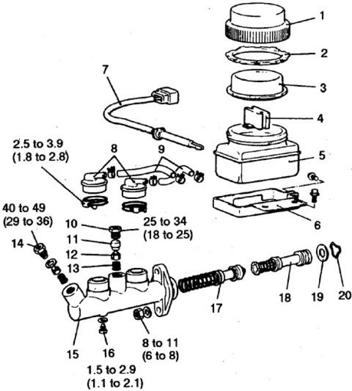
1. Tank cap; 2. Washer; 3. Diaphragm; 4. Float; 5. Tank; 6. Holder; 7. Sensor; 8. Fittings; 9. Hose; 10. Plug; 11. Saddle; 12. Valve; 13. Spring; 14. Valve body; 15. Cylinder; 16. Limit bolt; 17, 18. Pistons with springs; 19. Retaining ring; 20. Spring
Brake Master Cylinder Parts (1987-98)
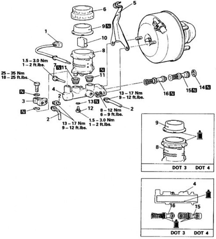
N – subject to replacement during disassembly
1. Liquid level sensor connector; 2. Tube fittings; 3. Connector; 4. Master cylinder; 5. Bracket
Adjusting the booster rod protrusion:; 6. Tank cap; 7. Bolt; 8. Tank; 9. Diaphragm; 10. Float; 11. Compaction; 12. Limit bolt; 13. Gasket; 14. Retaining ring; 15, 16. Pistons with springs
Removal and installation
1. Remove liquid from the tank.
2. Disconnect the wire from the fluid level indicator.
3. Disconnect the brake hydraulic tube fittings from the cylinder.
4. Unscrew the nuts and remove the cylinder.
5. Installation is carried out in reverse order.
6. Tighten all connections to the required torques.
7. Remove air from the hydraulic drive.
Disassembly and assembly
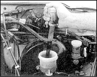
1. Remove liquid from the tank.
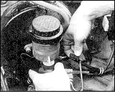
2. Disconnect the fluid level sensor connector.
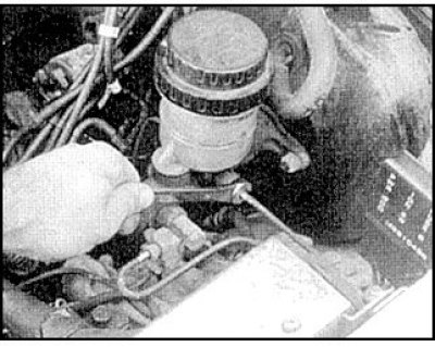
3. Disconnect the side brake pipe.
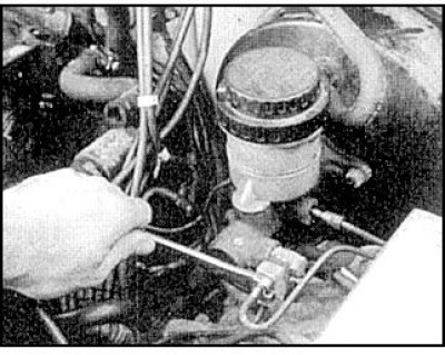
4. Disconnect the front brake pipe.
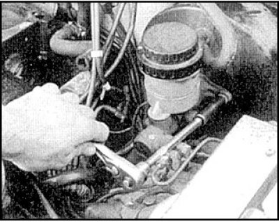
5. Unscrew the nuts.
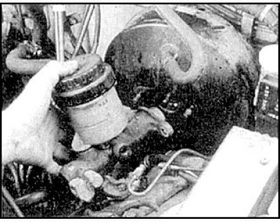
6. Remove the cylinder.
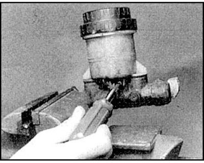
7. Clamp the cylinder in a vice by the flange.
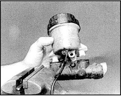
8. Unscrew the bolt and remove the tank.
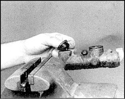
9. Unscrew the union nuts and remove the gaskets.
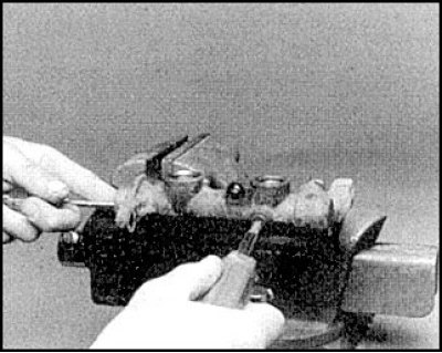
10. Remove the piston stop bolt.
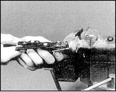
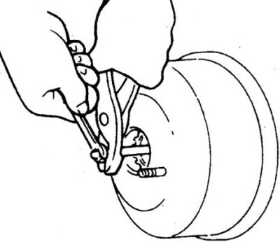
11. Remove the retaining ring.
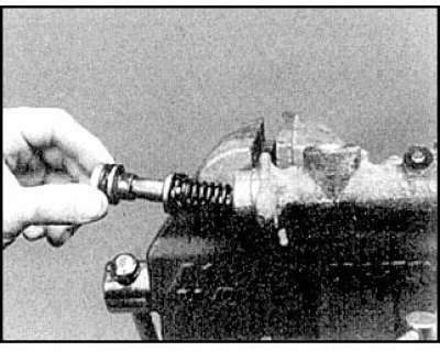
12. Remove the first piston (do not bend the piston).
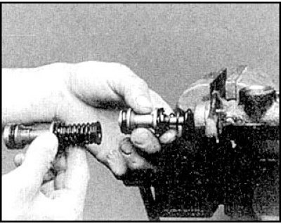
13. Remove the second piston.
[The article is based on data from the website mitsubishiman.ru]
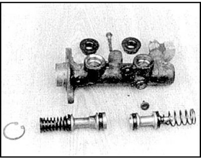
14. When disassembling, pay attention to the order of the parts.
15. Assembly is carried out in reverse order, taking into account the following.
16. Check the cylinder diameter in 6 places in mutually perpendicular directions. If the measurement spread exceeds 0.025 mm, replace the cylinder assembly.
17. Check the gap between the piston and the cylinder, which should be no more than 0.15 mm, otherwise replace the cylinder assembly.
18. Replace all seals.
19. Tighten all connections on the cylinder to the required torques.
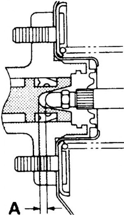
20. Before installing the cylinder, determine the gap A using the formula A = B – C – D.
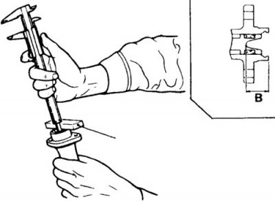
21. To determine A, measure the distance B through a plate with an accurately measured thickness.
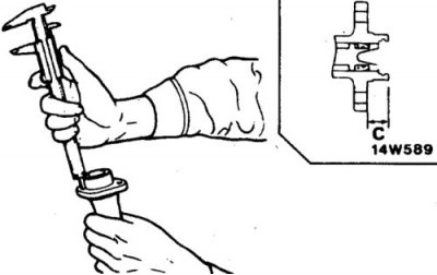
22. Measure the distance C.
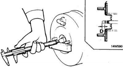
23. Then measure the distance D through the plate with the accurately measured thickness.
24. Calculate distance A. The gap should be 0.1–0.15 mm.
25. If necessary, adjust clearance A by rotating the brake booster rod and measuring distance D.
26. When finished, bleed the brakes.