



Contents: Removal and installation ⤓ Disassembly and assembly of the…⤓ Remove the retaining ring while…⤓
Removal and installation
Note: The engine control unit monitors the signal from the brake booster vacuum sensor and sets a diagnostic code if it is faulty. For checking the brake booster vacuum sensor, see the chapter "Fuel injection system".
- Before removing parts, drain the brake fluid.
− The parts are removed in the order of numbers shown in the figure "Removing the master brake cylinder and brake booster".
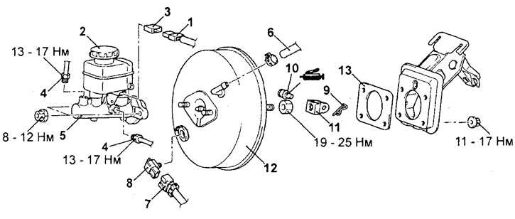
Removal the master brake cylinder and brake booster. 1 - brake fluid level sensor connector, 2 - reservoir, 3 - brake fluid level sensor, 4 - brake pipe, 5 - brake master cylinder, 6 - vacuum hose (with built-in check valve), 7 - vacuum booster vacuum sensor connector, 8 - vacuum booster vacuum sensor, 9 - cotter pin, 10 - pin, 11 - fork, 12 - brake booster, 13 - gasket.
− Installation of parts is carried out in the reverse order of removal.
- When installing parts, pay attention to the following operations:
1. Installing the vacuum hose.
Place the vacuum hose onto the fitting until it stops against the hexagon of the fitting with the color mark on the hose facing forward, then secure the hose with a clamp.
2. Before installing the seal and master cylinder, adjust the clearance between the brake booster rod and the primary piston.
a) Determine the distance "A" as shown in the figure.
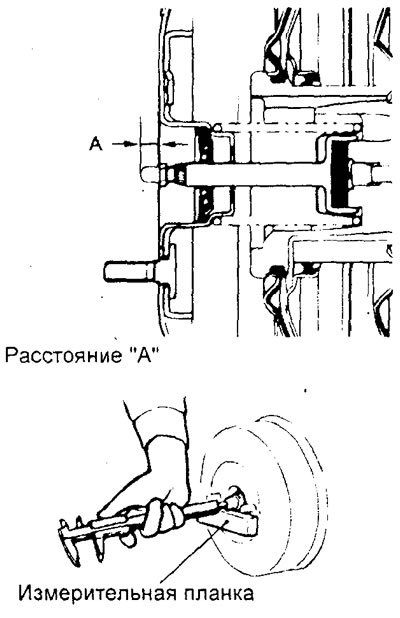
Nominal value "A" - 9.18 - 9.43 mm
Note: When creating a vacuum on the brake booster of 66.7 kPa, the distance "A" will be 10.28 - 10.53 mm.
b) If the measured value does not correspond to the nominal value, adjust it by changing the length of the brake booster rod by turning the rod adjusting screw. Using a spanner or tool head, turn the tappet adjusting screw while holding the rod groove with a special tool, as shown in the figure.
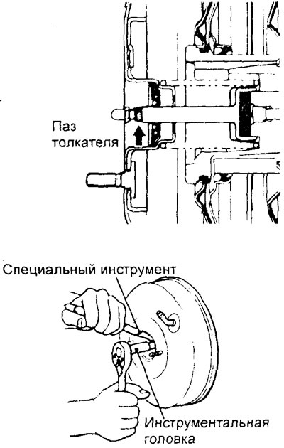
- After completing the installation of the parts, perform the following operations:
- a) Fill with brake fluid.
- b) Remove air from the brake hydraulic system.
- c) Adjust the brake pedal.
Disassembly and assembly of the brake master cylinder
− The parts are removed in the order of numbers shown in the figure "Disassembling the master brake cylinder".
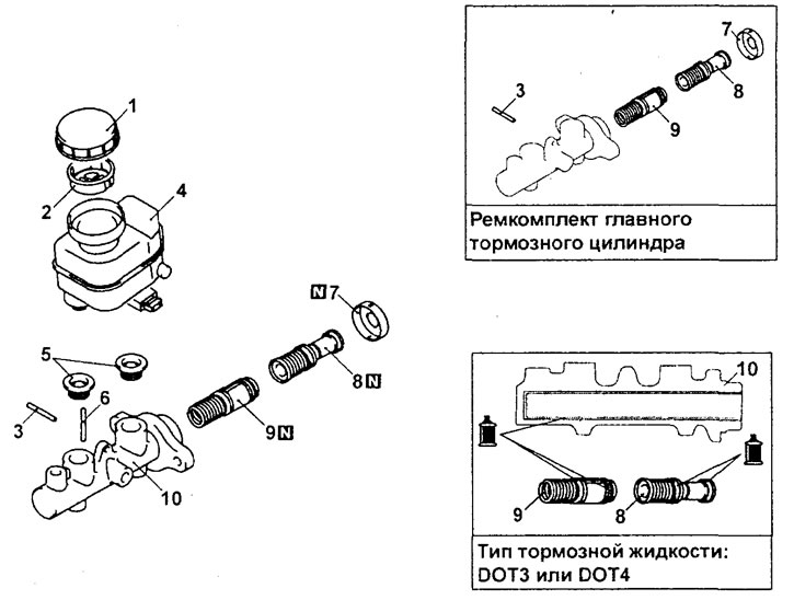
Disassembling the master brake cylinder. 1 - reservoir cover, 2 - filter, 3 - pin, 4 - brake hydraulic system reservoir, 5 - sealing sleeve, 6 - pin, 7 - holder, 8 - primary piston assembly, 9 - secondary piston assembly, 10 - brake master cylinder housing.
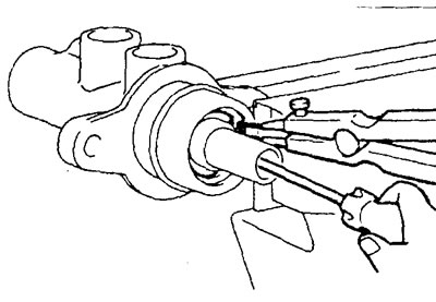
- When removing parts, pay attention to the operation of removing the piston retaining ring.
Remove the retaining ring while pressing on the piston.
− Installation of parts is carried out in the reverse order of removal.