



Contents: Checking and replacing brake pads ⤓ Checking the brake disc ⤓ Checking the thickness of brake discs ⤓ Checking and correcting the runout…⤓
Checking and replacing brake pads
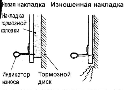
Note: When the brake pad lining thickness decreases to 2, the wear indicator comes into contact with the brake disc and makes a squealing sound while driving to warn the driver about the need for a regular replacement of the brake pads.
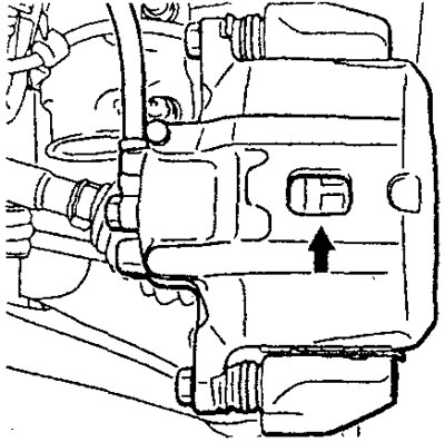
1. Measure the thickness of the brake shoe lining through the special service hole in the brake caliper.
Nominal value - 10 mm
The maximum permissible value is 2 mm
Attention:
- If the lining thickness of any pad is less than the maximum permissible value, replace the brake pads as a set, and also replace the brake pads on the opposite wheel of the same axle at the same time.
- If there is a noticeable difference in the thickness of the brake pad linings on the left and right sides of the caliper, check the smoothness of the caliper movement along the guide and stop pin bushings.
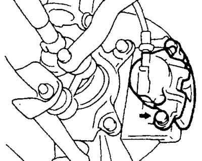
2. Remove the guide pin bolt. Lift the caliper assembly and hang it on the wire.
Caution: Do not remove the special grease from the guide and lock pins and do not allow dirt to get on the lock pin.
3. Remove the following parts from the caliper bracket.
- brake shoe and wear indicator assembly,
- brake shoe,
- brake shoe retainers,
- internal lining,
- outer lining.
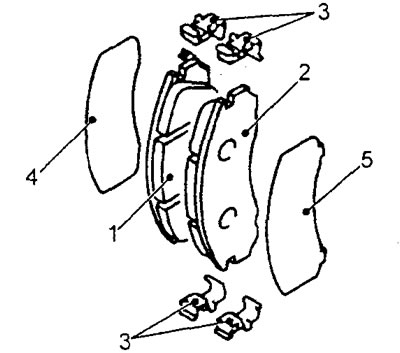
Brake mechanism parts. 1 - brake shoe and wear indicator assembly, 2 - brake shoe, 3 - shoe retainer, 4 - inner lining, 5 - outer lining.
4. With the brake pads removed, use a spring dynamometer to measure the resistance to rotation of the wheel hub in the forward direction.
5. Install the brake pads onto the disc brake caliper bracket and secure them with clamps.
6. Measure the resistance to rotation of the wheel hub when rotating in the forward direction. Determine the magnitude of the resistance force to rotation of the wheel hub with disc brakes installed (the difference between the measured values).
Checking the brake disc
Caution: To ensure proper operation of disc brakes, special attention must be paid to compliance with technical requirements when servicing disc brakes.
Note: Before performing restoration operations (before machining) of the brake disc, the following parameters must be checked.
1. Absence of scratches, rust, wear and impregnation of the disc surface with wear products of the linings.
a) If the car has not been used for some time, the part of the disc surface that has not been in contact with the brake pads will become covered with rust, which will lead to increased noise and vibration.
b) If grooves and scratches that have appeared on the surface of the disc as a result of intensive wear are not removed before installing new brake pads, normal contact between the disc and the brake pad linings will not be ensured.
2. No beating or wear of the brake disc.
Excessive disc runout or wear will result in increased resistance to pressing the brake pedal due to pulsation of the wheel brake cylinder piston.
3. Change in thickness (non-parallelism) of the brake disc.
If the thickness of the brake disc is not uniform around the perimeter, this will lead to vibration of the brake pedal.
4. Warping (non-flatness) of the brake disc.
Improper maintenance or overheating will cause the brake disc to warp (become uneven).
Checking the thickness of brake discs
1. Using a micrometer, measure the thickness of the brake disc at eight points approximately every 45° at a distance of 10 mm from the outer edge of the disc.
Nominal value - 24.0 mm
The maximum permissible value is 22.4 mm
Note: The difference in brake disc thickness between any two measurement points must not exceed 0.06 mm.
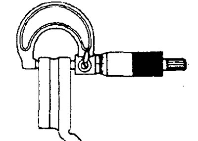
2. If the thickness of the brake disc is less than the maximum permissible value, remove it and install a new one. If the difference in the thickness of the brake disc between different measurement points exceeds the maximum permissible value, it is necessary to either replace the brake disc or process it on a special lathe.
Checking and correcting the runout of the front brake disc
1. Remove the disc brake caliper assembly, lift and secure the brake aside with wire.
2. Inspect the surface of the disc for deep scratches, rust and cracks. Clean the disc thoroughly and remove all rust.
3. Place a dial indicator approximately 5 mm from the outer edge of the brake disc and measure the disc runout.
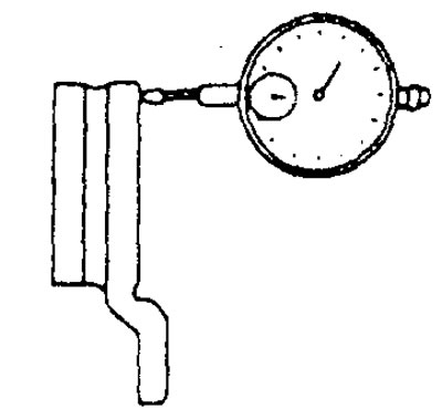
The maximum permissible value is 0.06 mm
4. If the runout value of the brake disc corresponds to the maximum permissible value or exceeds it, try changing the relative position of the disc and the wheel hub, then measure the runout again.
a) Before removing the brake disc, make marks with chalk on both sides of the wheel hub bolt at the point of maximum runout.
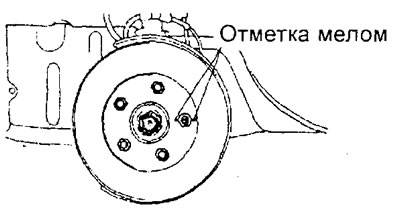
b) Remove the brake disc and install a dial indicator as shown in the figure. Measure the axial clearance of the hub bearing by moving the hub axially.
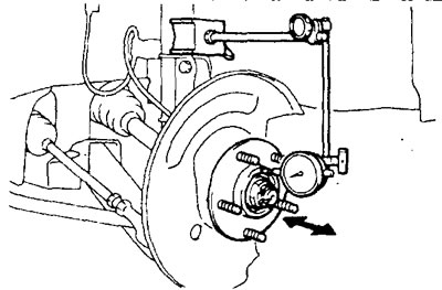
The maximum permissible value is 0.05 mm
c) If the axial clearance is equal to or exceeds the maximum permissible value, disassemble the hub and steering knuckle assembly and check the parts (see chapter "Front drive shafts").
d) If the axial clearance in the hub bearing does not exceed the maximum permissible value, then change the position of the brake disc on the hub (turn the brake disc 180° from the chalk mark), install it on the hub and repeat the measurement of the brake disc runout.
5. If the operations performed do not eliminate the increased runout of the disc, then it is necessary to replace the brake disc or process it on a special lathe.