



Removal and installation
− The parts are removed in the order of numbers shown in the figure "Removing the brake pedal".
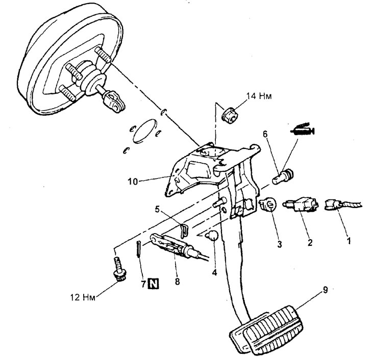
Removal the brake pedal. 1 - brake light switch connector, 2 - brake light switch, 3 - adjuster sleeve, 4 - pedal travel limiter, 5 - locking pin, 6 - pin with hole for cotter pin, 7 - cotter pin, 8 - selector lock cable connection, 9 - brake pedal pad, 10 - brake pedal and brake pedal mounting bracket.
− Installation of parts is carried out in the reverse order of removal.
- After completing the installation of the parts, adjust the brake pedal.
Checking the brake light switch
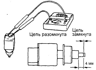
1. Connect a multimeter to the terminals of the brake light switch and check the condition of the circuit between the terminals of the switch with the switch rod pressed and released.
Information copied from the website MitsubishiMan
2. The brake light switch is in good condition if the circuit is open when the plunger is pressed so that the length of the protruding part of the plunger from the end of the threaded part of the switch housing is no more than 4 mm, and if the circuit is closed when the plunger is released.