



Contents: Checking the indicator "ABS" ⤓ Reading fault codes using a tester ⤓ Table. ABS system fault codes. ⤓ Reading fault codes without a tester ⤓ Clearing fault codes without a tester ⤓ Removal codes by disconnecting the…⤓ Checking the actuators of the…⤓ Checks on the ABS control unit…⤓ Checking the circuit condition and…⤓
Certain phenomena during operation of the anti-lock braking system (ABS) On models equipped with the ABS system, deviations may occur from time to time that do not indicate a malfunction.
1. Sound of system functionality check.
After starting the engine, sometimes a dull sound may be heard from the engine compartment. This is a sign that the ABS system is undergoing control procedures to check its functionality.
2. Sounds of the ABS system operation.
a) The sound of the pump motor running inside the ABS hydraulic unit (howling sound).
b) Sound accompanied by vibration of the brake pedal (scraping).
c) Sounds in the vehicle's chassis as a result of periodically pressing and releasing the brake pedal.
Note: A dull knock in the chassis usually comes from the suspension, and a squeal from the tires.
3. Operation of the ABS system (long braking distance).
On gravel and snowy roads, the braking distance of a car with ABS may sometimes exceed that of a car with standard brakes. Therefore, it is recommended that drivers do not be overconfident and, for safety reasons, reduce their speed when driving on such roads.
Attention:
- The ABS system may operate even without sudden braking when turning the steering wheel at high speed, when driving on a road with a low coefficient of adhesion or when driving on uneven surfaces.
4. Feeling vibration on the brake pedal.
Vibration on the brake pedal occurs due to the operation of the ABS electromagnetic valves and is a sign of normal operation of the ABS system.
Checking the indicator "ABS"
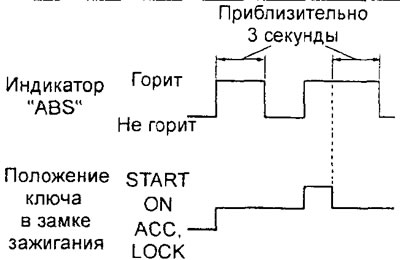
1. Turn the ignition key to the "ON" position and make sure that the "ABS" indicator comes on for three seconds and goes out.
2. Turn the ignition key to the "START" position to start the engine and make sure that the "ABS" indicator is on.
3. Turn the ignition key from the "START" position to the "ON" position and make sure that the "ABS" indicator lights for three seconds and then goes out.
Caution: The "ABS" indicator may remain on after the key is returned to the "ON" position until the vehicle speed reaches 8-10 km/h. This situation is possible only if fault codes #21-24, #41-44, #53-55 were recorded in the ABS electronic control unit memory due to a previous fault. In this case, the ABS electronic control unit leaves the indicator on until a check is performed to confirm that the fault related to this code has been eliminated or self-corrected.
4. If the operation of the "ABS" indicator differs from that described above, check for fault codes.
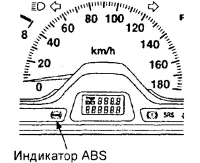
Models with standard instrument cluster.
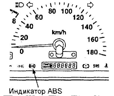
Models with high-contrast instrument cluster.
Reading fault codes using a tester
1. Turn the ignition key to the "OFF" position.
2. Connect the tester to the diagnostic connector under the instrument panel and read the fault codes. Attention: follow the instructions for using the tester.
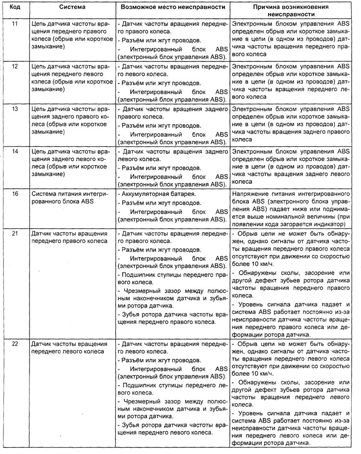
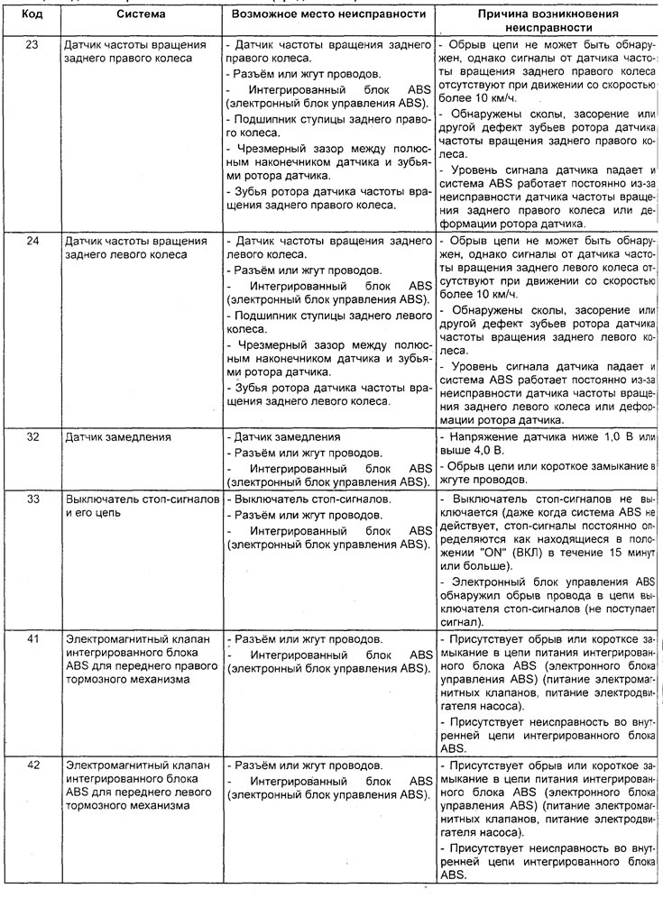
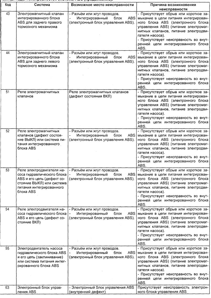
3. Determine the fault based on the read code and make the necessary repairs or troubleshooting (see the table "ABS system fault codes").
Note: If the ABS system is not operating normally and diagnostic codes are output, first check the cause given in the code description, then check for a fault (poor contact) in the connector or a break in the wiring harness. If no fault is found, replace the ABS ECU with a known good one, then clear the codes and perform a road test.
4. After completing the repair or correcting the malfunction, turn the ignition key to the "OFF" position.
Table. ABS system fault codes.
5. Clear the fault codes from the electronic control unit memory using the tester reset button.
6. Check that there are no fault codes.
7. Disconnect the tester from the diagnostic connector.
Reading fault codes without a tester
1. Turn the ignition key to the "OFF" position.
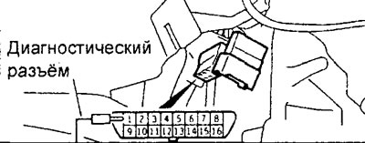
2. Using a special test lead, connect the "DOT" terminal of the diagnostic connector to ground.
3. Turn the ignition key to the "ON" position and read the fault codes by the number of flashes of the "ABS" indicator.
Note:
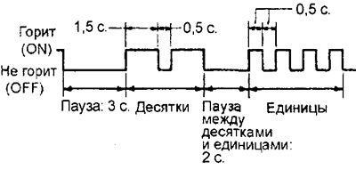
- The fault code consists of two digits, the first digit is determined by the initial series of flashes, then after a pause of two seconds, a second series of flashes follows, which corresponds to the second digit of the code.
- If there are two or more fault codes, the lowest code will be displayed first, followed by the others in ascending order. There will be a 3-second pause between codes.
4. If there is no fault, the indicator will flash at 0.25 second intervals.
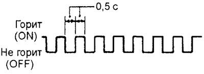
5. Determine the fault based on the read code and make the necessary repairs or troubleshooting (see the table "ABS system fault codes").
Note:
- If the ABS system is not operating normally and diagnostic codes are output, first check the cause given in the code description, then check for a fault (poor contact) in the connector or a break in the wiring harness. If no fault is found, replace the ABS integrated unit (ABS electronic control unit) with a known good one, then clear the codes and perform a road test.
- Diagnostic code #16 is cleared from the ABS integrated unit (ABS electronic control unit) memory when the ignition switch is turned to the "ACC" position or when the system returns to a normal condition.
- Diagnostic codes #52 and #63 are cleared from the ABS integrated unit (ABS electronic control unit) memory when the ignition switch is turned to the "ACC" position.
6. After completing the repair or correcting the malfunction, turn the ignition key to the "OFF" position.
7. Delete the fault codes from the memory of the electronic control unit (see the subsection "Delete fault codes without a tester").
8. Check that there are no fault codes.
9. Disconnect the special wire from the "DCT" terminal of the diagnostic connector.
Clearing fault codes without a tester
Clearing codes using the brake pedal (Pajero Sport)
Note: If the ABS function is blocked (emergency ABS system operation mode), it is impossible to delete fault codes from the ABS control unit memory using this method.
1. Turn the ignition key to the "OFF" position.
2. Using a special test lead, connect the "DCT" terminal of the diagnostic connector to ground.
3. Press the brake pedal (set the brake light switch to the "ON" position).
The text of the article was taken from the website MitsubishiMan
4. Turn the ignition key to the "ON" position. Within 3 seconds of turning the ignition key to the "OFF" position, release the brake pedal (set the brake light switch to the "OFF" position). Then press and release the brake pedal ten times in succession (see the figure "Indicator Operation Diagram When Clearing ABS DTCs Using the Brake Pedal").
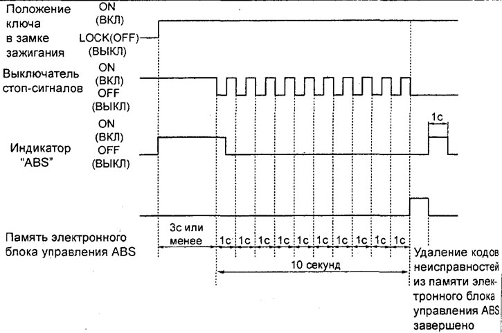
Indicator operation diagram when clearing ABS fault codes using the brake pedal.
Note: When the fault code erase mode is activated, the "ABS" indicator will light up.
Removal codes by disconnecting the cable from the battery
Disconnect the cable from the negative battery terminal for 10 seconds or more, then reconnect the cable.
Checking the actuators of the hydraulic unit using a tester
1. To force the actuator to turn on, use the "ACTUATOR TEST" function of the tester.
Attention:
- The actuator test cannot be performed if the ABS emergency mode is activated or the vehicle is moving. If the speed of one of the wheels exceeds 10 km/h, the actuator test will be terminated automatically.
- If the ABS indicator starts to flash, you must stop checking the actuators.
2. When the ABS electromagnetic valve is activated (FR, FL, RR, RL) for each channel of the hydraulic block, in addition to the valve itself, the pump electric motor will be activated.
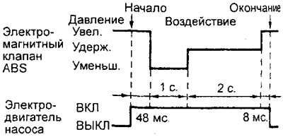
Checks on the ABS control unit connector
Checking the voltage at the terminals of the ABS electronic control unit connector
Attention: it is not allowed to measure the voltage at the terminals of the ABS electronic control unit for three seconds after the ignition is turned on, since during this period the initial check of the ABS system is performed by the self-diagnostic system.
1. Turn the lock as shown in the figure.
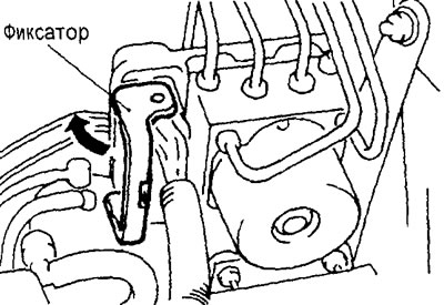
2. Press the latches and disconnect the connector.
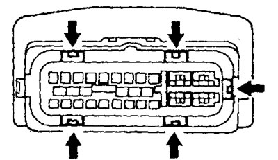
3. Check the voltage between the ground terminals of the ABS control unit and the other terminals of the unit with the connector connected (see the table "Checking the voltage at the terminals of the ABS electronic control unit connector").
Checking the circuit condition and resistance at the terminals of the wiring harness connector
1. Before checking the circuit condition and resistance, turn the ignition key to the "OFF" position and disconnect the ABS control unit connectors.
2. Check the voltage between the terminals of the connectors on the wire harness side (see the table "Checking the terminals of the wire harness connector").