
Type of self-diagnosis system
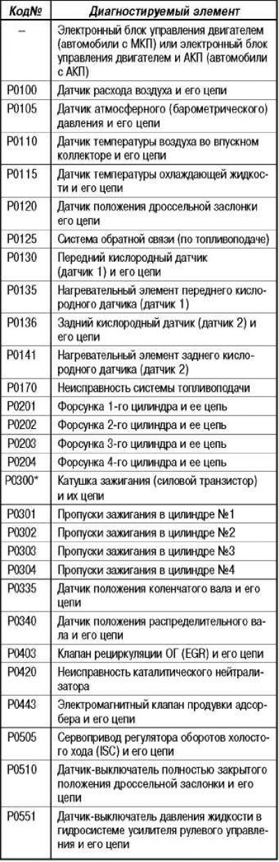
On models with an EOBD or OBD-II type self-diagnosis system, the standard diagnostic code consists of one letter and 4 digits (For example: «P00G0»). The numbering of such codes is continuous, i.e. fault codes for various systems are not repeated.
On models with an OBD-II system, a new function has been added to the engine control unit «freeze frame data» (freeze frame data). If a malfunction is detected, the self-diagnosis system will record the appropriate diagnostic code and record the current parameters of the main components and engine systems at the moment («freeze frame data»). This data, read by the tester, can make it easier to analyze the fault conditions.
Features of diagnostics using a tester
The algorithm of the Mitsubishi diagnostic system is slightly different from the standard algorithm (OBD II protocol), therefore, it is recommended to use the MUT-II tester to perform correct diagnostics.
It is recommended to connect a tester (MUT-II) with the ignition off, as a malfunction of the electronic control units may occur.
Before connecting the tester to the diagnostic connector, make sure that the condition and shape of the connector pins are correct.
Diagnostic connector
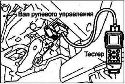
One standard 16-pin main diagnostic connector was installed in the car (located under the instrument panel).
Explanations on the operation of the engine malfunction indicator lamp («CHECK ENGINE»)
The control lamp lights up for a few seconds immediately after the ignition is turned on to show that the lamp itself is functioning normally.
Further (after starting or with the engine running) The warning lamp comes on to alert the driver that a malfunction has been detected by the self-diagnosis system.
Attention: if the control lamp lights up due to a malfunction of the control unit, then communication between the tester and the control unit cannot be established, and there is no way to read diagnostic codes.
In the event of a critical failure (a serious defect in the fuel injection or emission control system) the control lamp will be on constantly when the vehicle is moving until the fault code is cleared after the fault has been repaired (those. after repair).
Note. Deleting a fault code is not a troubleshooting
The control lamp will go out when the ignition is turned off (key: «OFF»).
Conditions under which a lit indicator lamp («CHECK ENGINE») can go out at the signal of the control unit when the ignition is on (fault code stored)
Note. For any malfunction, the cycle means start-stop the engine or three trips (road test car) during which the fault is monitored.
For a fault in the transmission: if the engine control unit has not detected a fault within three cycles under the appropriate modes and conditions (see code occurrence conditions).
For a fault in the exhaust emission system (skip flashes in cylinders): if the engine control unit did not detect a malfunction during the cycle under similar engine operating conditions (engine speed, coolant temperature, etc.), at which the fault was first detected.
Explanations on the operation of the self-diagnosis system
The engine control unit monitors input/output signals (some permanently, others only under certain conditions). If a permanent or for a predetermined period of time a malfunction of the system is detected, or if after the first incorrect signal the engine control unit receives several more similar signals, the engine control unit will perceive this as a malfunction, write the corresponding fault code into memory and send signal to the output of the self-diagnosis system.
Note. Usually, if the control unit has detected a malfunction, then the control lamp will light up and the malfunction code will be written only after the engine is restarted and the same malfunction is detected again.
For some faults, the warning lamp will come on and the corresponding fault code, marked with «*», will be recorded the first time it is encountered.
Since the storage device (engine control unit memory) is powered directly from the battery, the diagnostic results are retained even when the ignition key is turned to the «OFF». Fault codes will be erased when the battery terminal or engine control unit connector is disconnected. In addition, fault codes are erased if, with the ignition on, (key in position «ON») a signal will be sent from the tester to the engine control unit to clear the trouble codes.
Attention! If with the ignition on (key in position «ON») disconnect the connector of any sensor, then the control unit will perceive this as a malfunction and the corresponding code will be written to the memory of the control unit. In this case, clear the trouble codes.
Standard Troubleshooting Chart
Simulate symptoms to check for their presence and determine the nature and conditions of occurrence (engine operating mode, operating conditions, etc.).
Read fault codes and determine the causes of the fault, the components to be tested and the order in which they should be tested.
Check the input signals of the engine control unit using a tester or motor tester. If the signals are normal, then the corresponding sensor (element) serviceable. Proceed to check the next component,
Check the output signals of the engine control unit using a motor tester and check the operation of the actuators (drives) using the ACTUATOR TEST function of the tester. If the signals of the engine control unit and the drive are normal, then the drive control is normal. Move on to the next component.
If the signals of the engine control unit are normal, then check and, if necessary, repair the electrical wiring of the system components. After repair, check the signals of the engine control unit again. If the signals are OK this time, then check the input and output signals for the next component to be tested.
If the wiring is in order, but the input and output signals of the engine control unit are not correct, then check the individual components of the system and, if necessary, repair or replace them. After repair, check the signals of the engine control unit again. If the signals are OK this time, check the signals for the next component to be tested.
Recheck for symptoms and repair
If, as a result of checking the suspect wiring circuit and specific components, no defects are found, but the input and output signals of the engine control unit deviate from the norm, then more closely evaluate the symptoms (the initial diagnosis may have been incorrect or incomplete). When checking further, try to expand the troubleshooting area to other groups of components (repair if necessary).
Try to simulate the symptoms of the problem to be sure that the problem has been fixed. Eliminate the cause of the malfunction to prevent the defect from reappearing.
Check of a control lamp of indication of malfunction of the engine («CHECK ENGINE»)
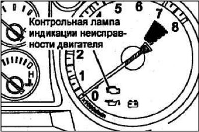
If a malfunction occurs in any of the following elements of the distributed sprinkler system (MPI) engine warning light comes on («CHECK ENGINE»). If this light stays on while the engine is running, check for a DTC. In this case, it must be remembered that the engine malfunction indicator lamp will burn for 5 seconds after the ignition key is turned to the position «ON» («ON»).
Elements of the fuel injection system (or conditions), in case of failure (or not fulfillment) of which the engine malfunction indicator lamp lights up («CHECK ENGINE»)
Note. If the control lamp lights up due to a malfunction of the electronic engine control unit (cars with manual gearbox) or an electronic engine control unit and automatic transmission (vehicles with automatic transmission), communication between MUT-II and ECU (cars with manual gearbox) or an electronic engine control unit and automatic transmission (vehicles with automatic transmission) is not possible, the diagnostic trouble code cannot be read.
Note. As soon as the electronic engine control unit (cars with manual gearbox) or an electronic engine and automatic transmission control unit (vehicles with automatic transmission) detected a malfunction, the engine malfunction indicator lamp lights up every time the engine is restarted and the same malfunction is displayed again. However, for the position marked with «*» in the table, the control lamp lights up only once at the first detection of a malfunction.
Note. After the engine malfunction indicator lamp comes on, it will turn off when the following conditions are met:
Note. When the engine control unit (cars with manual gearbox) or an electronic engine and automatic transmission control unit (vehicles with automatic transmission) for three times identified a malfunction in the transmission.
Note. Sign «*» in the table: in this case «once» indicates the period from start to stop of the engine.
Note. In the misfire judgment mode when the driving conditions of the vehicle (engine speed, coolant temperature, etc.) similar to the condition in which this fault was first detected.
Note. «Sensor 1» means that the sensor is installed closer to the engine, and «sensor 2» means the sensor is installed further, compared to the first, from the engine.
Reading Diagnostic Trouble Codes
Make sure the battery is in good condition, as fault detection is not possible when the battery voltage is low.
Turn off all additional equipment.
Set the automatic transmission selector lever to the position «N».
Attention! Do not disconnect the battery until the diagnostic results are completely read, as the fault code will be deleted from the memory of the electronic control unit when the battery or control unit connector is disconnected.
Turn the ignition key to position «OFF» («OFF»).
When checking with a tester, connect the tester to the diagnostic socket under the instrument panel.
Attention! When connecting or disconnecting the tester «ignition» should be off (ignition key in position «OFF» («OFF»).
Turn on the ignition and read the diagnostic codes.
After completing the test, turn the ignition key to the position «OFF» (OFF) and then disconnect the tester from the diagnostic socket.
Clearing Diagnostic Trouble Codes
Turn the ignition key to position «OFF».
If a tester is used, then connect it to the diagnostic socket and erase the codes.
If the tester is not in use, disconnect the cable from the negative battery terminal for 10 seconds or more.
After disconnecting the wire from the negative terminal of the battery, the contents of the memory of electronic control units of other systems will be lost.
Turn the ignition key to position «ON», then verify that the normal status code is displayed.
After warming up the engine, let it idle for at least 10 minutes.
Diagnosis in mode «Diagnosis 2»
Using MUT-II, switch the electronic control unit to diagnostic mode «Diagnosis 2».
Do a road test.
Read diagnostic codes and perform repair procedures to correct the problem found.
Turn the ignition key to the OFF position (OFF), and then move it back to position «ON» («ON»).
Note. When the ignition is turned off, the engine control unit will switch the test mode from «Diagnosis 2» on mode «Diagnosis 1».
Erase diagnostic codes.
Checking Using Modes «DATA LIST» (data table) And «ACTUATOR TEST» (check of executive devices) MUT-II
Check using DATA LIST modes (data table) And «ACTUATOR TEST» (check of executive devices) MUT-II.
In the event of a malfunction, check the vehicle's electrical wiring, relevant components and parts.
After repair, recheck using the MUT-II and verify that the repair has returned the incorrect input and output signal to normal.
Clear diagnostic trouble codes from the memory of the electronic control unit.
Disconnect the MUT-II, restart the engine and road test to make sure the problem is corrected.
Data «Freeze» («FREEZE FRAME»)
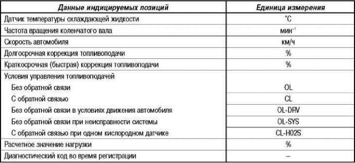
When the engine control unit (cars with manual gearbox) or an electronic engine and automatic transmission control unit (vehicles with automatic transmission) detects a malfunction and stores a diagnostic trouble code, it also stores the current state of the engine. This function is called «freeze frame» («FREEZE FRAME»). Analyzing data «freeze frame» with MUT-II, effective troubleshooting can be carried out. Displayed data positions «freeze» shown in the table below.
Note. If several faults are detected in several systems, only the one fault that was detected first is stored.
List of displayed positions
Test readiness state
Electronic engine control unit (cars with manual gearbox) or an electronic engine and automatic transmission control unit (vehicles with automatic transmission) controls the following main diagnosed elements, judges their condition (OK/Faulty) and remembers the dynamics of changes in their technical condition. The latter can be read using MUT-II (if the electronic control unit had information about the technical condition of some element before, MUT-II displays «Complete» - «Done»).
Finally, if diagnostic trouble codes are erased, or when the battery is disconnected, information about the technical condition of the element is also erased at the same time (the memory of the electronic control unit is reset).
- Catalytic converter: P0420.
- Oxygen sensor: P0130.
- Oxygen sensor heating element: P0135, P0141.
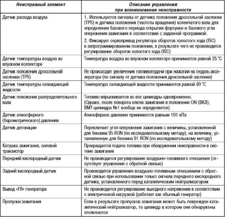
Reference table for emergency operation
When the self-diagnosis system detects a malfunction of one of the main sensors, the system switches to emergency control mode («FAIL SAFE FUNCTION»), so that the car can continue moving (to the station service).
Check on the terminals of the connector of the electronic engine control unit
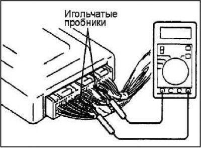
Connect needle probes (MB991223 test lead harness or paper clip) to voltmeter probes:
According to the test table, insert the needle test probe (paperclip) to each terminal of the connector of the electronic engine control unit (ITUC) or engine control unit and automatic transmission (AKP) from the wiring harness side and measure the voltages, checking their values in accordance with the test chart.
Note. Carry out voltage measurement when connected to the electronic engine control unit (ITUC) or engine control unit and automatic transmission (AKP) connector.
Note. For ease of connection to the terminals of the connector, you can extend the electronic engine control unit (ITUC) or an electronic engine and automatic transmission control unit (AKP).
Note. It is allowed to carry out checks in a different order than that specified in the table for checking.
Attention! Short circuit positive (+) probe connected to the output of the connector, on «mass» can cause damage to the wiring, sensor, electronic engine control unit (ITUC) or an electronic engine control unit and automatic transmission (AKP), or all of these elements. Be very careful not to let this happen.
If the voltmeter detects any deviation from the nominal value, then check the corresponding sensor, actuator and corresponding wires, then repair or replace.
After repair or replacement of a part (node) recheck the voltage with a voltmeter to make sure the problem is corrected.