



Contents: Operating principle of the system ⤓ Checking the Exhaust Gas…⤓ Checking the Exhaust Gas…⤓ Checking the EGR valve servo (engine…⤓ Checking the resistance of the servo…⤓ Checking the operation of the servo…⤓ Cleaning the EGR valve ⤓ Removal and installation the EGR…⤓
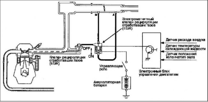
The exhaust gas recirculation (EGR) system reduces nitrogen oxide (NOx) emissions. When the air-fuel mixture burns at a high temperature in the combustion chamber, a large amount of nitrogen oxide (NOx) is formed. The EGR system directs part of the exhaust gases from the exhaust port of the cylinder head through the intake manifold back into the combustion chambers, thereby reducing the combustion temperature of the air-fuel mixture, which results in a decrease in the concentration of nitrogen oxides. The degree of exhaust gas recirculation is regulated by the EGR valve so as not to impair the stability of the engine.
Operating principle of the system
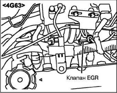 | 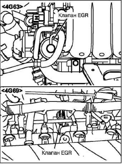 |
The EGR valve is closed and exhaust gas recirculation does not occur under one of the following conditions: In all other modes, the EGR valve is open and exhaust gas recirculation occurs.
Checking the Exhaust Gas Recirculation (EGR) System
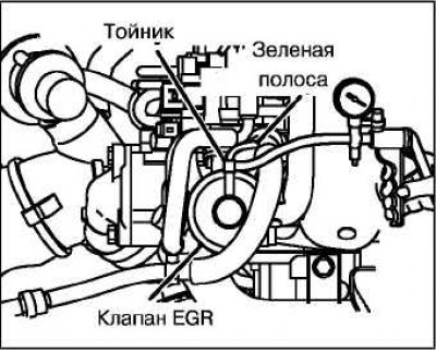
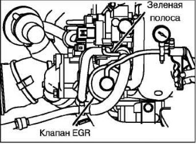
Disconnect the vacuum hose (with a green stripe) from the EGR valve and connect a hand vacuum pump to it through a tee.
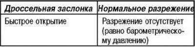
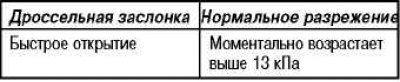
By increasing the speed on a cold and warmed up engine, check the vacuum condition.
Cold engine (Engine coolant temperature no more than 20°C)
Warm engine (Engine coolant temperature not less than 80°C)
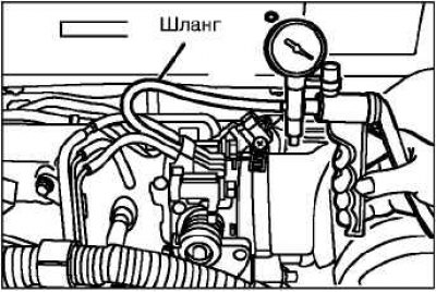
Disconnect the reducing tee.
Connect a hand vacuum pump to the EGR valve.
Check to see if the engine idles erratically or stalls when you apply a vacuum of 30 kPa or more.
Checking the Exhaust Gas Recirculation (EGR) Valve
Remove the EGR valve and check for sticking of the valve stem, deposits, etc. If any abnormalities are found, clean the valve with a suitable solvent so that the valve stem seats properly.
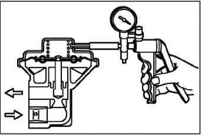
Connect a hand vacuum pump to the EGR valve.
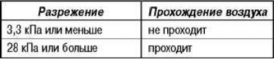
Create a vacuum of 67 kPa and check if it is maintained.
Create a vacuum and check if air passes through the EGR valve.
Replace the valve gasket and tighten the screws to the specified torque.
Tightening torque: 22 Nm.
Checking the EGR vacuum hose fitting
Disconnect the vacuum hose (with the white stripe) from the fitting on the throttle body and connect a hand vacuum pump to it.
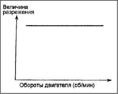
Start the engine and check that the vacuum value remains constant as the engine speed increases.
Note: If the vacuum reading changes as engine speed increases, the EGR fitting in the throttle body is likely clogged and needs to be cleaned.
Checking the EGR solenoid valve
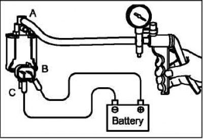 | 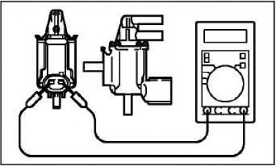 |
Disconnect the vacuum hoses (with yellow, white and green stripes) from the solenoid valve.
Note: When disconnecting vacuum hoses, always make alignment marks first so that the hoses will be in their original positions when reconnected.
Disconnect the electrical connector.
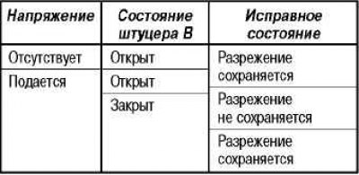
Connect the hand vacuum pump to the fitting where the hose with the white stripe was attached.
Check the operation of the valve by creating a vacuum with the battery disconnected and connected to the valve terminals.
Checking the EGR valve servo (engine 4G69)
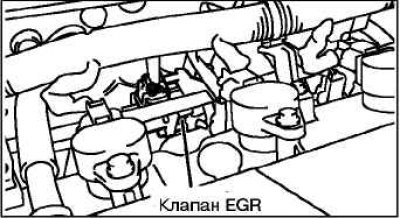
Make sure that the sound of the EGR valve servo (stepper motor) operating can be clearly heard when the ignition is turned on (without starting the engine).
If the sound of the EGR valve servo working is not heard, then check the power supply circuits of the servo. If the power supply circuit is in good order, then the servo itself or the electronic engine control unit may be faulty.
Checking the resistance of the servo drive winding
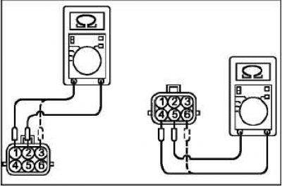
Disconnect the EGR valve servo connector.
Measure the resistance between terminal "2" and terminals "1" or "3" of the servo connector.
Nominal resistance: 20–24 Ohm (at 20°C).
Measure the resistance between terminal "5" and terminals "4" or "6" of the servo connector.
Nominal resistance: 20–24 Ohm (at 20°C).
Replace the gasket and tighten the valve mounting bolts to the specified torque.
Tightening torque: 24 ±3 Nm.
Checking the operation of the servo drive
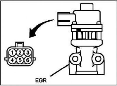
Remove the EGR valve servo.
Connect the test lead harness to the EGR servo connector.
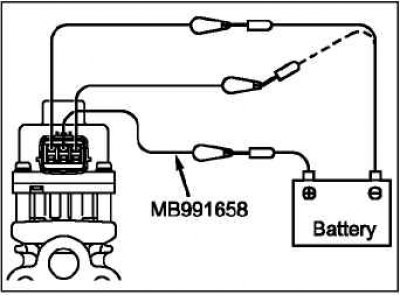
Connect the wire from the positive terminal of the power source (voltage approximately 6V) to terminal "2" of the servo connector.
Connect the wire from the negative terminal of the 6V power supply to the terminals "1" and "3" of the connector. At the same time, check whether a slight vibration of the operating stepper motor is felt.
Connect the wire from the positive terminal of the power source (voltage approximately 6 V) to terminal "5" of the servo connector.
Connect the wire from the negative terminal of the 6V power supply to the terminals "4" and "6" of the connector. At the same time, check whether a slight vibration of the operating stepper motor is felt.
If, as a result of these checks, a slight vibration of the operating servo drive is felt, then it is considered to be in good working order.
Replace the gasket and tighten the valve mounting bolts to the specified torque.
Tightening torque: 24 ±3 Nm.
Cleaning the EGR valve
Remove and inspect the EGR valve for sticking or clogging. If necessary, clean the valve with a wire brush.
Warning: Do not use solvent for cleaning, as it may cause malfunctions if it gets on the servo drive.
Replace the gasket and tighten the valve mounting bolts to the specified torque.
Tightening torque: 24±3 Nm
Removal and installation the EGR valve
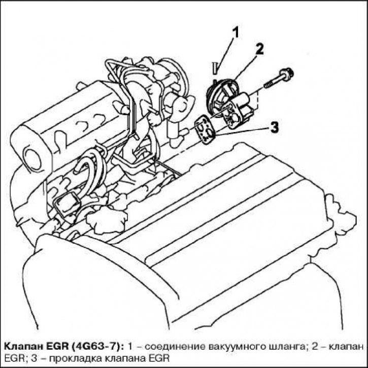
Remove the air cleaner cover and air inlet hose (4G63-7).
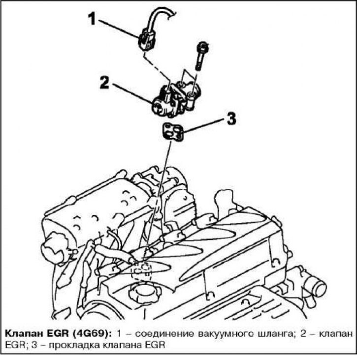
Remove the resonator (4G69).
Installation of parts is carried out in the reverse order of removal.
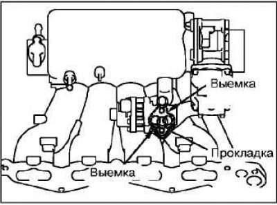
When installing the parts, pay attention to the EGR valve gasket installation operation.
Install the valve gasket with the notched sides facing as shown in the illustration.
Install the air cleaner cover and air intake hose.
Install the resonator.