



Contents: General information ⤓ Checking the EGR valve servo (except…⤓ Cleaning the EGR valve ⤓ System check (engine 4G15-MPI) ⤓ Checking the vacuum control valve…⤓ Checking the EGR valve (4G15-MPI…⤓ Checking the EGR valve vacuum line…⤓ Checking the EGR solenoid valve…⤓ Removal and installation the EGR…⤓ Removal and installation the EGR…⤓
General information
1. The EGR system reduces nitrogen oxide (NOx) emissions. When the air-fuel mixture burns at high temperatures in the combustion chamber, large amounts of nitrogen oxide (NOx) are formed. The EGR system directs part of the exhaust gases from the exhaust port of the cylinder head through the intake manifold back into the combustion chambers, thereby reducing the combustion temperature of the air-fuel mixture, which results in a decrease in the concentration of nitrogen oxides.
2. The amount of exhaust gas recirculated is regulated by the EGR valve servo (except for the 4G15-MPI engine) or the EGR valve (4G15-MPI engine) so as to prevent deterioration in engine performance.
3. The EGR valve is closed and exhaust gas recirculation does not occur under one of the following conditions: low engine coolant temperature, engine idling, or the throttle valve is fully open. In all other conditions, the EGR valve is open and exhaust gas recirculation occurs.
Checking the EGR valve servo (except for 4G15-MPI engine)
Checking the servo drive by the sound of its operation
1. Make sure that the sound of the EGR valve servo (stepper motor) operating is clearly audible when the ignition is turned on (without starting the engine).
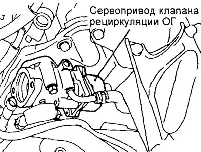
Engine 4G15-GDI.
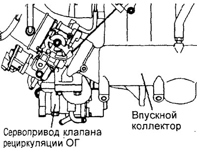
Engine 4G93-GDI.
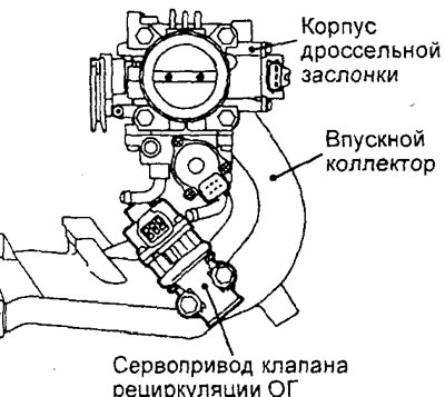
Engine 4G93-MPI.
2. If the sound of the EGR valve servo operating is not heard, check the servo power supply circuits. If the power supply circuit is OK, then the servo itself or the engine control unit may be faulty.
Checking the resistance of the servo drive winding
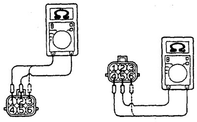
1. Disconnect the EGR valve servo connector.
2. Measure the resistance between terminal "2" and terminal "1" or "3" of the servo connector.
Nominal resistance:
- GDI - 10-20 Ohm (at 20°C)
- 4G93 - MPI 20-24 Ohm (at 20°C)
3. Measure the resistance between terminal "5" and terminal "4" or "6" of the servo connector.
Nominal resistance:
- GDI - 10-20 Ohm (at 20°C)
- 4G93 - MPI 20-24 Ohm (at 20°C)
Checking the operation of the servo drive
1. Remove the EGR valve servo.
2. Connect the test lead harness to the EGR servo connector.
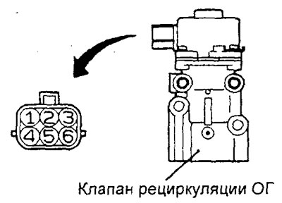
3. Connect the wire from the positive terminal of the power source (voltage approximately 6V) to terminal "2" of the servo connector.
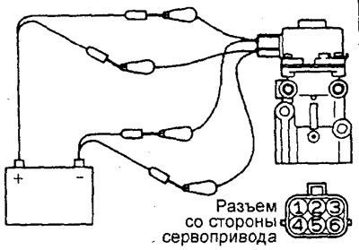
4. Connect the wire from the negative terminal of the 6V power supply to the terminals "1" and "3" of the connector. At the same time, check whether a slight vibration of the operating stepper motor is felt.
5. Connect the wire from the positive terminal of the power source (voltage approximately 6V) to terminal "5" of the servo connector.
6. Connect the wire from the negative terminal of the 6V power supply to the terminals "4" and "6" of the connector. At the same time, check whether a slight vibration of the operating stepper motor is felt.
7. If, as a result of these checks, a slight vibration of the operating servo drive is felt, then it is considered to be in good working order.
8. Replace the gasket and tighten the valve mounting bolts to the specified torque.
Tightening torque: 16-22 Nm
Cleaning the EGR valve
1. Remove and check the EGR valve for sticking or clogging. If necessary, clean the valve with a wire brush.
Caution: Do not use solvent for cleaning, as it may cause malfunction if it gets on the servo.
2. Replace the gasket and tighten the valve mounting bolts to the specified torque.
System check (engine 4G15-MPI)
1. Disconnect the vacuum hose (with a green stripe) from the EGR valve and then connect a hand vacuum pump through a T-fitting between the valve and the hose.
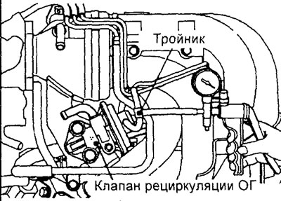
2. Perform the check when the engine is cold (coolant temperature 20°C or less).
Press the accelerator pedal sharply, increasing the engine speed, and make sure that a vacuum is not created (atmospheric pressure 0 kPa).
3. Perform the check when the engine is warm (coolant temperature 80°C or higher).
Press the accelerator pedal sharply, increasing the engine speed, and check that the vacuum temporarily increases instantly to 13 kPa (100 mmHg) or more.
4. Disconnect the tee and connect a hand vacuum pump directly to the EGR valve. Close the open vacuum hose with a plug.
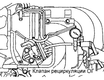
5. Create a vacuum of more than 27 kPa when the engine is idling, and check whether the engine stalls or idles erratically.
Checking the vacuum control valve (4G15-MPI engine)
1. Disconnect the vacuum hose (with white stripe) from the valve and connect a hand vacuum pump to the valve nipple.
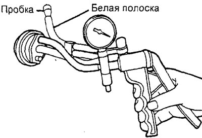
2. Close the disconnected vacuum hose with a plug.
3. Start the engine and let it idle.
4. Check the vacuum.
Nominal value is approximately 23 kPa
Checking the EGR valve (4G15-MPI engine)
1. Remove the EGR valve and check for sticking of the valve stem, carbon deposits, etc. If there are deposits, clean the valve with solvent so that the valve stem seats correctly.
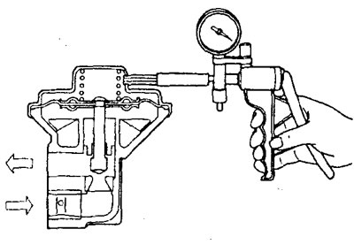
2. Connect a hand vacuum pump to the EGR valve diaphragm fitting.
Note: If the valve diaphragm has two fittings, close the second fitting with a plug.
3. Using the pump, create a vacuum of 67 kPa and check that it is maintained.
4. Check the air flow through the valve (through the exhaust gas supply channel).
a) Create a vacuum of less than 7 kPa and make sure that no air passes through the valve.
b) Create a vacuum of more than 27 kPa and make sure that air passes through the valve.
5. Replace the gasket and tighten the valve mounting bolts to the specified torque.
Tightening torque: 17 - 25 Nm
Checking the EGR valve vacuum line (4G15-MPI engine)
Note: Before checking, warm up the engine until the coolant temperature reaches 80-95°C.
1. Disconnect the vacuum hose (with a green stripe) from the EGR vacuum hose fitting (on the throttle body) and connect the hose to a hand vacuum pump.
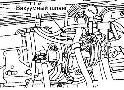
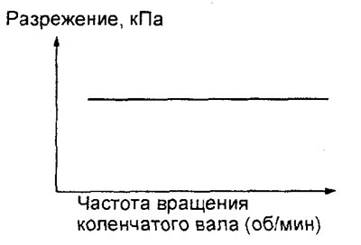
2. Start the engine and check that the vacuum value remains almost constant as the crankshaft speed increases.
Note: if the amount of vacuum varies with increasing engine crankshaft speed, it is likely that there is a clogging of the vacuum hose connector of the exhaust gas recirculation system in the throttle body, and it must be cleaned.
Checking the EGR solenoid valve (4G15-MPI engine)
Note: When disconnecting the vacuum hose, first make alignment marks so that when connecting the hose, the bull is in its original position.
1. Disconnect the vacuum hoses from the solenoid valve.
2. Disconnect the wiring harness connector from the solenoid valve.
3. Connect the hand vacuum pump to the connection "A" from which the hose (with a green stripe) was disconnected.
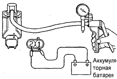
4. Create a vacuum using a vacuum pump and check the operation of the solenoid valve.
a) Check that the vacuum in the valve is maintained when battery power is connected to the valve terminals.
b) Check that the vacuum in the valve decreases when the battery power is not connected to the terminals.
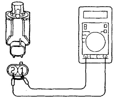
5. Measure the resistance between the terminals of the solenoid valve.
Nominal resistance - 29 - 35 Ohm (at 20°C)
Removal and installation the EGR valve servo (except for the 4G15-MPI engine)
Before you begin removing parts, perform the following operations:
- a) (GDI engines) Drain the coolant.
- b) Remove the air filter assembly.
The parts are removed in the order of the numbers indicated in the figure "Removing the EGR valve servo drive".
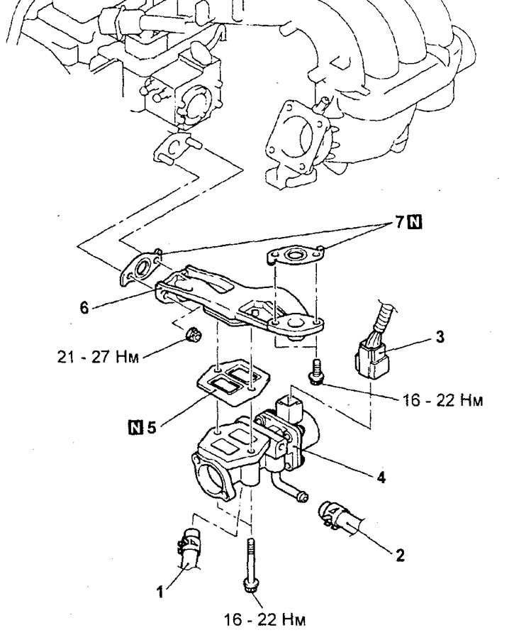
Removal the EGR valve servo (engine 4G15-GDJ). 1 - cooling system hose, 2 - cooling system hose, 3 - wiring harness connector of the exhaust gas recirculation valve servo, 4 - exhaust gas recirculation valve servo, 5 - gasket, 6 - exhaust gas recirculation system tube and exhaust gas recirculation valve servo bracket, 7 - exhaust gas recirculation system tube gasket.
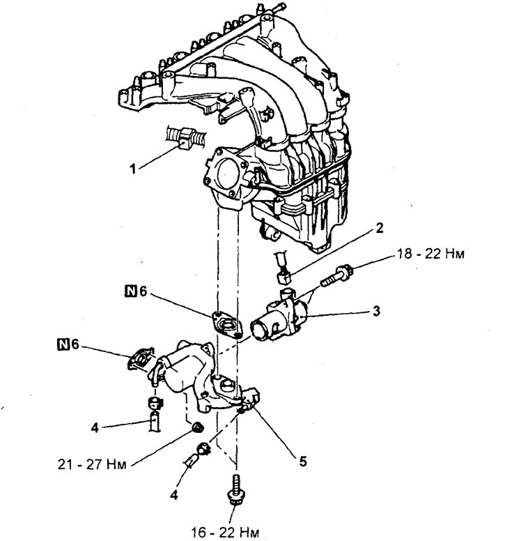
Removal the EGR valve servo (4G93-GDI engine). 1 - wiring harness retainer, 2 - wiring harness connector for the exhaust gas recirculation valve servo (remove the intake manifold), 3 - exhaust gas recirculation valve servo, 4 - cooling system hose, 5 - exhaust gas recirculation system tube and exhaust gas recirculation valve servo bracket, 6 - exhaust gas recirculation system tube gasket.
(GDI engine) When removing parts, pay attention to the operation of removing the fuel pump protective cover.
Raise the gearbox using a transmission telescopic stand, creating a gap between the engine and the windshield wiper panel, and remove the fuel injection pump protective cover.
Installation of parts is carried out in the reverse order of removal.
(Except for 4G93-GDI engine) When installing the parts, pay attention to the installation operation of the gasket and the EGR valve servo.
a) Install the EGR valve servo gasket as shown in the figure.
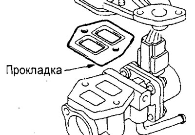
Engine 4G15-GDI.
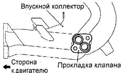
Engine 4G93-GDI.
b) Tighten the servo drive mounting bolts to the specified torque.
Tightening torques:
- GDI engine - 16-22 Nm
- MPI engine - 21 - 27 Nm
- After completing the installation of the parts, perform the following operations:
- a) Install the air filter assembly.
- b) (GDI engines) Fill with coolant
Removal and installation the EGR valve (4G15-MPI engine)
Before you begin removing parts, remove the air cleaner assembly.
The parts are removed in the order of the numbers indicated in the figure "Removing the EGR valve".
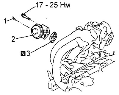
Removal the EGR valve. 1 - vacuum hose connection, 2 - EGR valve, 3 - EGR valve gasket.
Installation of parts is carried out in the reverse order of removal.
After completing the installation of the parts, install the air filter assembly.