



Location of components and vacuum hoses
1. The location of components and vacuum hoses may vary depending on engine type, year of manufacture and vehicle modification.
2. The location of the components of the electronic control system, the general diagram of the injection system and the exhaust gas toxicity reduction system are given in the chapter "Fuel injection system".
3. Decoding the colors of the hoses and hose strips (marked in circles) shown in the diagrams "Location of vacuum hoses".
| Designation | Hose color |
| IN | black |
| G | green |
| L | blue |
| R | red |
| W | white |
| Y | yellow |
Precautions to take when checking
1. Check various devices only after adjusting the engine.
2. Check the condition of the hoses (make sure that there are no disconnected hoses, damaged hoses or hoses connected incorrectly).
3. Make sure that there is no blockage in the hoses, pipelines and fittings, check for cracks and damage to the hoses and pipelines.
4. When replacing hoses, always install the new hose in the same position (direction) as the original hose.
5. After completing maintenance, check the connections as described in the repair manual and in accordance with the warning on the sticker.
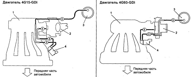
Location of vacuum hoses. 1 - intake manifold, 2 - throttle body, 3 - adsorber, 4 - adsorber purge electromagnetic valve.
The text of the article was taken from the website www.MitsubishiMan.ru