



Contents: General information ⤓ Checking the purge system of the…⤓ Checking the vacuum hose nipple for…⤓ Checking the purge solenoid valve of…⤓ Removal and installation the adsorber ⤓
General information
1. When the vehicle is moving, the fuel vapors accumulated in the adsorber are directed through the vacuum or electromagnetic purge valve of the adsorber, the vacuum hose and the fitting of the throttle body into the intake manifold and then burn in the engine.
2. The electronic control unit (based on signals from the mass air flow sensor, coolant temperature sensor, barometric pressure sensor and intake air temperature sensor) opens and closes the electromagnetic valve of the adsorber purge, regulating the flow of fuel vapors into the intake manifold. At low coolant temperature or at low air flow (for example, at idle), the electronic engine control unit switches off the electromagnetic valve, and the valve blocks the flow of fuel vapors into the intake manifold. This ensures stable engine operation when it is not warmed up or is operating under low load, but also reduces toxic emissions.
Note: Sensor testing procedures are provided in the Fuel Injection System chapter.
Checking the purge system of the adsorber
1. Disconnect the vacuum hose (for MPI engines with red stripe) from the intake manifold (GDI engines) or throttle body (MPI engines) and connect the hose to a large vacuum pump.
2. Close the plug on the purge channel nipple of the adsorber from which the vacuum hose was disconnected.
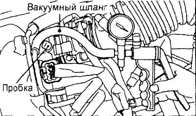
Engine 4G15-GDI.
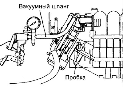
Engine 4G93-GDI.
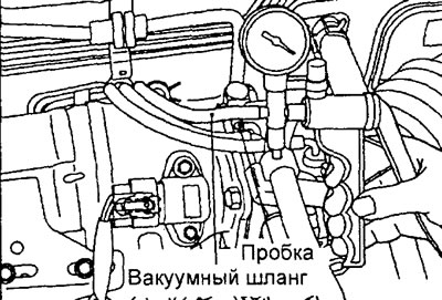
Engine 4G15-MPI.
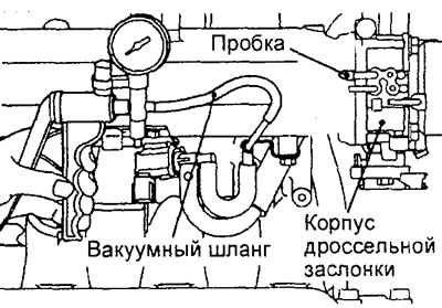
Engine 4G93-MPI.
3. Perform a system check (engine condition and vacuum) when the engine is not warmed up (coolant temperature 40°C or less). Using a vacuum pump, create a vacuum of 53 kPa (400 mmHg) when the engine is idling.
a) When the engine is idling, the vacuum must be maintained.
b) When the engine is running at 3000 rpm, the vacuum must be maintained.
4. Perform a system check (engine condition and vacuum) when the engine is warm (coolant temperature 80°C or more). Using a vacuum pump, create a vacuum of 53 kPa (400 mmHg) when the engine is idling.
a) When the engine is idling, the vacuum must be maintained.
b) 3 minutes after starting the engine, when the engine is running at 3000 rpm, the vacuum will decrease.
Checking the vacuum hose nipple for purging the adsorber
1. Disconnect the vacuum hose from the canister purge port fitting on the intake manifold (GDI engines) or throttle body (MPI engines).
Note:
- - For GDI engines, the vacuum hose is black.
- - For MPI engines, vacuum hose with red stripe.
2. Connect a hand vacuum pump to the nipple.
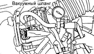
Engine 4G15-GDI.
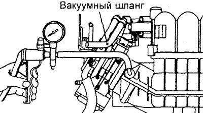
Engine 4G93-GDI.
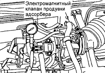
Engine 4G15-MPI.
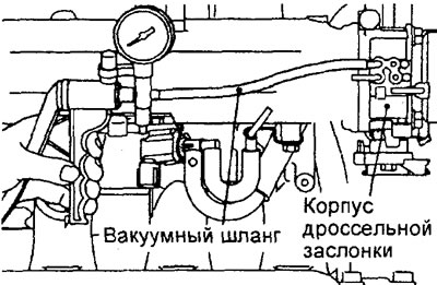
Engine 4G93-MPI.
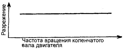
3. Start the engine and check that as the engine crankshaft speed increases, the vacuum remains almost constant.
Note: If a vacuum is not created, there is likely deposits in the vacuum hose fitting channel on the intake manifold and it needs to be cleaned.
Checking the purge solenoid valve of the adsorber
Note: When disconnecting the vacuum hose, always make alignment marks first so that the hose is in its original position when reconnecting.
1. Disconnect the vacuum hose (for MPI engines with a red stripe) from the solenoid valve nipple.
2. Disconnect the wiring harness connector from the solenoid valve.
3. Connect a hand vacuum pump to the "A" port of the solenoid valve from which the vacuum hose was disconnected.
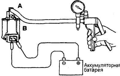
4. Create a vacuum using a vacuum pump and check the operation of the solenoid valve.
a) Check that the vacuum in the valve is maintained when power is not connected to the valve terminals.
b) Check that the vacuum in the valve decreases when battery power is connected to the valve terminals.
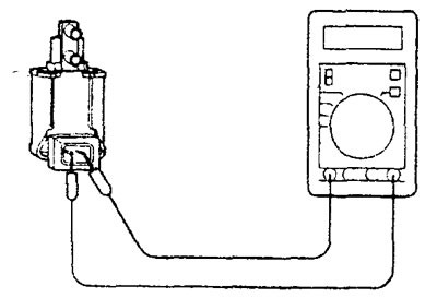
5. Measure the resistance between the terminals of the solenoid valve.
Nominal value (at 20°C) - 30-34 Ohm
Removal and installation the adsorber
- Before starting to remove parts, remove the air filter assembly.
− The parts are removed in the order of the numbers indicated in the figure "Removing the adsorber assembly".
− Installation of parts is carried out in the reverse order of removal.
- After completing the installation of the parts, install the air filter assembly.
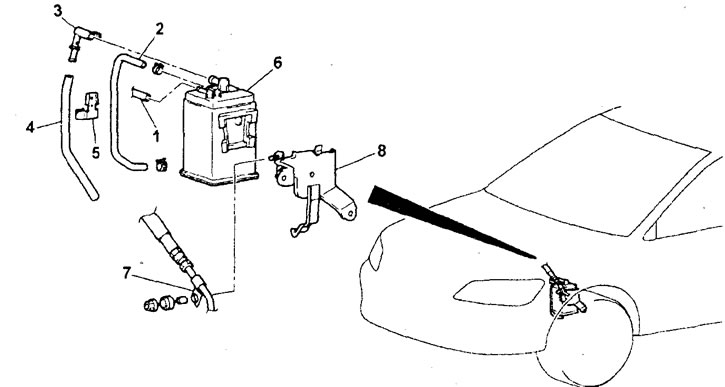
Removal the adsorber assembly. 1 - fuel vapor recovery system hose connection, 2 - canister purge hose, 3 - ventilation tube, 4 - canister purge hose, 5 - hose retainer, 6 - canister, 7 - high-pressure fuel hose retainer, 8 - canister mounting bracket.