



Contents: Tank ⤓ Float chamber ventilation valve ⤓ Blow-off system ⤓ Thermovalve ⤓ Fuel tank filler cap ⤓ Overflow limiter ⤓ Fuel check valve ⤓
1. The fuel vapor emission control system is designed to prevent the release of fuel vapor from the fuel system into the atmosphere.
2. A typical fuel vapor emission control system consists of a tank, a float chamber ventilation valve, a purge system, an overflow limiter, a thermal valve, a non-return fuel valve, and a specially designed fuel tank filler cap (see illustration).
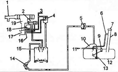
3.2a. Elements of the emission control system for carburetor models (standard). 1. Air filter, 2. Float chamber ventilation valve. 3. To thermal valve, 4. Purge valve, 5. Overflow limiter (two-way valve), 6. Overflow limiter (level tube), 7. Fuel tank filler cap, 8. Fuel tank filler pipe, 9. Fuel level sensor, 10. Thermal expansion volume, 11. Fuel (to carburetor), 12. Fuel tank, 13. Filter, 14. Fuel check valve, 15. Reservoir, 16. Hole, 17. Intake manifold, 18. Carburetor float chamber, 19. Carburetor.
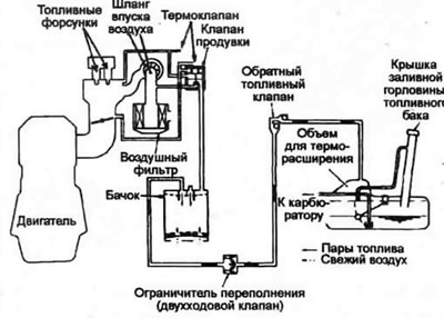
3.2b. Elements of the emission control system for TBI models (typical).
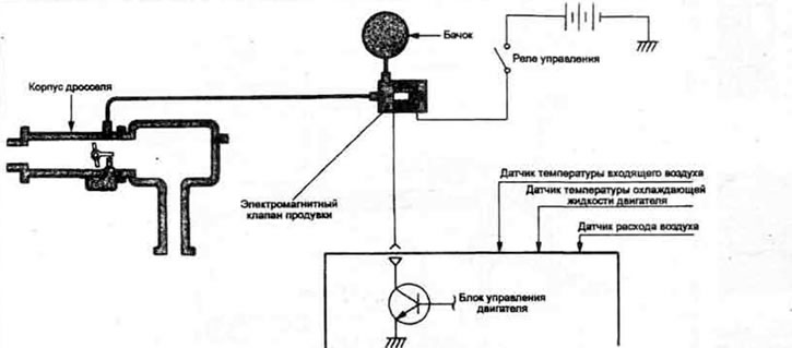
3.2c. Elements of the emission control system for 1.5L MPI models (typical).
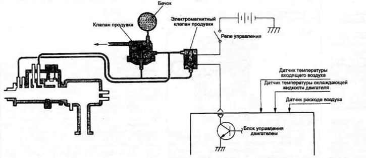
3.2d. Emission control system components for 1.6L MPI models (typical).
Tank
3. When the engine is turned off, the fuel vapors generated inside the fuel tank and in the float chamber of the carburetor are absorbed by the tank. During engine operation, the fuel vapors absorbed by the tank are sucked into the intake manifold through the scavenging system.
Float chamber ventilation valve
4. The float chamber ventilation valve controls the fuel vapors in the carburetor float chamber. When the engine is running, the vacuum in the intake manifold acts on the diaphragm and closes the float chamber ventilation valve so that the float chamber is connected to the ventilation channel. During engine operation, the diaphragm is held open by an electromagnetic valve (even when the vacuum in the intake manifold drops to atmospheric pressure) while the ignition is on. When the ignition is turned off, the electromagnetic valve closes, the float chamber ventilation valve opens and connects the carburetor float chamber to the tank, allowing fuel vapors to flow into it, where they remain until the next ignition is turned on.
Blow-off system
5. The purge system is closed when the engine is idling and prevents fuel vapors from entering the intake manifold. At high engine speeds, the purge system valve opens.
Thermovalve
6. The thermostatic valve, which controls the temperature of the engine coolant at the intake manifold, controls the purge system when the coolant temperature is below the set point. This reduces CO and HC emissions during engine warm-up. The thermostatic valve opens the purge system when the engine coolant temperature is above the set point. The thermostatic valve also controls the choke switch, EGR valve and choke tappet.
Fuel tank filler cap
7. The cover is equipped with a safety vacuum valve that prevents fuel vapors from escaping into the atmosphere.
Overflow limiter
8. A typical overflow limiter consists of two valves:
- a) Pressure valve which opens when the internal pressure in the fuel tank exceeds the normal pressure.
- b) Vacuum valve which opens when the internal pressure in the fuel tank is lower than normal pressure.
Fuel check valve
9. The non-return fuel valve prevents fuel leakage in the event of a vehicle rollover. The valve includes two balls. Under normal conditions, the fuel vapor release channel in the valve is open, but when the vehicle rolls over, one of the balls closes the fuel channel, preventing fuel leakage.