



Removal
- Before you begin removing parts, perform the following operations:
- a) Drain the coolant,
- b) (GDI engines) Remove the engine cover.
- c) Remove the air filter.
- d) Remove the throttle body.
- d) (GDI engines) Remove the ignition coils.
- e) (MPI engines) Remove the fuel rail assembly with injectors.
− The parts are removed in the order of numbers shown in the figure "Removing the intake manifold".
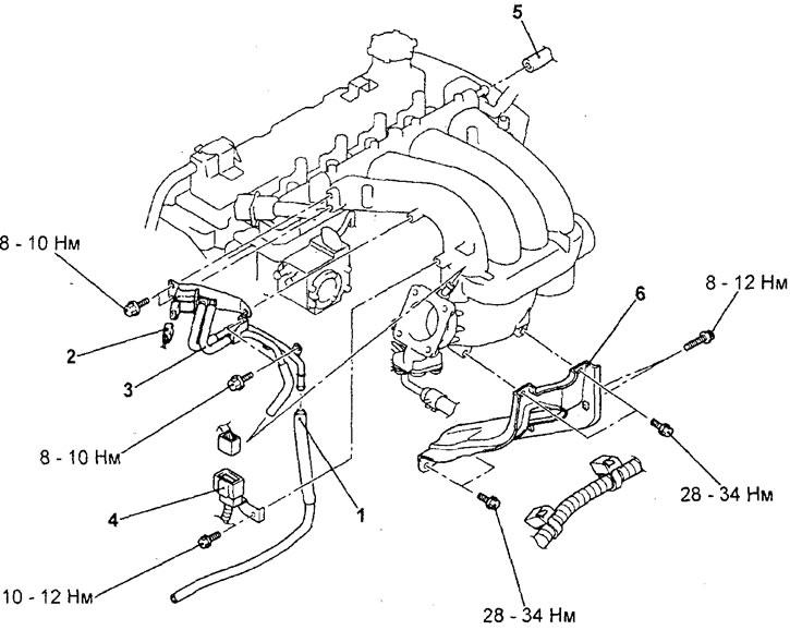
Removal the intake manifold (4G15-GDI engine). 1 - connection of the vacuum hose of the purge system of the adsorber, 2 - connector of the electromagnetic valve of the purge system of the adsorber, 3 - bracket of the electromagnetic valve of the purge system of the adsorber and vacuum tubes and hoses in assembly, 4 - connector of the servo drive of the EGR valve, 5 - hose of the forced crankcase ventilation system, 6 - rack of the intake manifold.
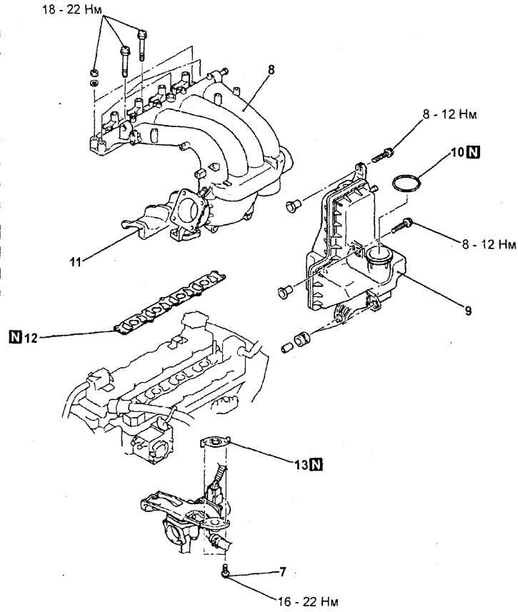
Removal the intake manifold (4G15-GDI engine, continued). 7 - EGR tube mounting bolt, 8 - intake manifold, 9 - intake manifold resonator, 10 - O-ring gasket, 11 - insulator, 12 - intake manifold gasket, 13 - EGR tube gasket.
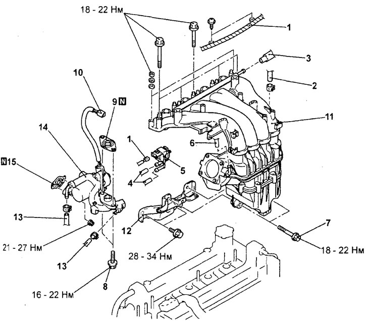
Removal the intake manifold (4G93-GDI engine). 1 - engine management system wiring harness, 2 - brake booster vacuum hose, 3 - forced crankcase ventilation system hose, 4 - vacuum hose, 5 - adsorber purge solenoid valve, 6 - adsorber purge system hose, 7 - intake manifold and intake manifold strut mounting bolt, 8 - bolt securing the exhaust gas recirculation system tube to the intake manifold, 9 - exhaust gas recirculation system tube gasket, 10 - connector of the servo drive of the exhaust gas recirculation valve, 11 - intake manifold assembly, 12 - intake manifold post, 13 - cooling system hose, 14 - exhaust gas recirculation system tube and exhaust gas recirculation valve servo drive assembly, 15 - exhaust gas recirculation system tube gasket.
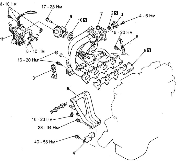
Removal the intake manifold (4G15-MPI engine). 1 - absolute pressure sensor in the intake manifold, 2 - ring gasket, 3 - knock sensor connector, 4 - power unit bracket, 5 - intake manifold strut, 6 - engine mount bracket, 7 - intake manifold, 8 - intake manifold gasket, 9 - EGR valve, 10 - EGR valve gasket, 11 - vacuum tubes and hoses assemblies.
- (4G15-GDI Engine) When removing parts, pay attention to the operation of removing the intake manifold.
Carefully separate the resonator from the intake manifold, then remove the intake manifold.
Examination
1. Check all parts for damage and cracks, if any are found, replace the part. Clean the parts if necessary. Caution: when cleaning, do not allow foreign particles to enter the intake channels of the cylinder head and intake manifold.
2. Check the condition of the intake manifold gasket.
3. Check for blockages in the vacuum bleed nipple holes, coolant passages, positive crankcase ventilation system passages, as well as exhaust gas passages and exhaust gas recirculation (EGR) system passages.
4. Using a straightedge and a set of feeler gauges, measure the non-flatness of the cylinder head mating surface, as well as the mating surfaces of the intake manifold.
Non-flatness of the mating surface under the gasket:
- Nominal - 0.15 mm or less
- Maximum permissible - 0.20 mm
5. If defects are found during inspection according to the above points, the part is subject to replacement.
Installation
− Installation of parts is carried out in the reverse order of removal.
- After completing the installation of the parts, perform the following operations:
- a) (MPI engines) Install the fuel rail assembly with injectors.
- b) (GDI engines) Install the ignition coils.
- c) Install the throttle body.
- d) Install the air filter.
- d) (GDI engines) Install the engine cover.
- e) Fill with coolant.
The text of the article was obtained from the website: MitsubishiMan