
Engine 2.0L
Removal and installation
1. Disconnect the battery from the ground. Drain the coolant and disconnect the radiator hose from the thermostat housing.
2. Remove the carburetor, marking all detachable hoses and wires.
3. Disconnect all vacuum hoses from a collector.
4. Turn away nuts, having greased them with the penetrating liquid. Displace the manifold with light strokes and remove.
5. Clear demountable planes of a collector and a head of cylinders. Check the deformation of the planes, grind the plane of the head if necessary (taking it off) and replace the manifold.
6. Installation is carried out in the reverse order. Replace gasket. Tighten the collector nuts with a torque of 22 Nm.
2.4L engine
2.4L Engine Intake Manifold
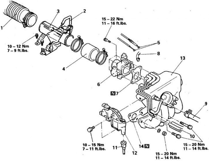
1. Air outlet; 2. Ventilation hose; 3. Inlet pipe; 4. Trumpet; 5. Throttle and kick-down control cables; 6. Throttle pipe; 7. Gasket; 8. Crankcase ventilation hose; 9. Brake booster hose; 10. Vacuum hose; 11. Wire; 12. Coil; 13. Leveling chamber; 14. Collector
Removal and installation
1. Decompress. To do this, disconnect the connector at the rear of the fuel tank, start the engine and, after stopping it, turn off the ignition.
2. Disconnect the battery from the ground. Drain the coolant and disconnect the radiator hose from the thermostat housing.
3. Designate and disconnect from a collector all hoses and wires. Carefully disconnect and plug the fuel lines.
4. Disconnect the coil wire from the ignition distributor.
5. Remove the equalizing chamber.
6. Remove the fuel distributor with injectors.
7. Remove the ignition distributor.
8. Turn away nuts and bolts and remove a collector.
9. Clear demountable planes of a collector and a head of cylinders.
10. Installation is carried out in the reverse order. Replace manifold and surge chamber gaskets. Tighten the manifold nuts to 16 Nm, starting with the nut in the middle of the manifold. Make the necessary adjustments.
2.6L engine
2.6L Engine Intake Manifold
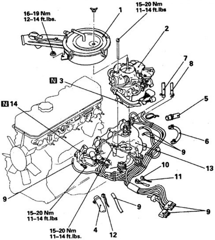
1. Filter; 2. Carburetor; 3. Gasket; 4. Upper radiator hose; 5. Fluid bypass hose; 6. Connecting hose; 7. Heater hose; 8. Brake booster hose; 9. Vacuum hose; 10. Air conditioner temperature sensor wire; 11. Temperature sensor wire; 12. Temperature gauge wire; 13. Collector; 14. Gasket
Removal and installation
1. Disconnect the battery from the ground. Remove the air filter.
2. Drain the coolant and disconnect the radiator hose from the thermostat housing.
3. Remove the carburetor.
4. Remove outlet pipe, thermostat and gasket.
5. Remove the secondary air filter and tube.
6. Remove the oil gauge.
7. Remove the air conditioning compressor. Take the unit to the side without disconnecting it from the line, and secure it. Remove compressor bracket.
8. Designate and disconnect from a collector and the thermostat all hoses and wires.
Carefully disconnect and plug the fuel lines. Take aside the wiring and hoses that interfere with the removal of the manifold.
9. Remove the recirculation valve.
10. Turn away nuts and remove a collector.
11. Clear demountable planes of a collector and a head of cylinders. Check the deformation of the planes, grind the plane of the head if necessary (taking it off) and replace the manifold. Install all sensors and valves on the new manifold.
12. Installation is carried out in the reverse order. Replace all gaskets and seals. Tighten the manifold nuts first by hand and then to 22 Nm, starting with the nut in the middle of the manifold. Tighten the bolts of the compressor bracket with a torque of 45 Nm, compressor - 24 Nm, thermostat - 12 Nm. Check operation of all gauges and control lamps on the panel of devices.
3.0 and 3.5L engines
Equalization chamber of the engine 3.0 l
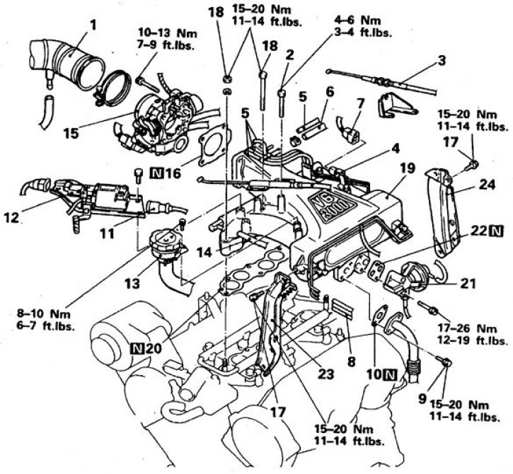
1. Air outlet; 2. Accelerator cable adjustment bolts; 3. Damper cable; 4. Accelerator cable; 5, 8. Vacuum hose; 6. Brake booster hose; 7. Connector for the temperature sensor of the recirculation valve; 9. Recirculation tube bolts; 10, 16, 20, 22. Gaskets; 11. Wire coil; 12. Coil; 13. Filler bracket; 14. Ventilation hose; 15. throttle pipe; 17, 18. Bolts and nuts; 19. Leveling chamber; 21. Recirculation valve; 23, 24. Racks
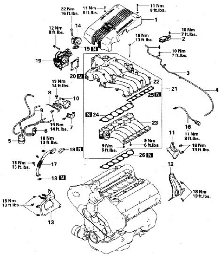
3.0L Engine Intake Manifold - Removable Parts
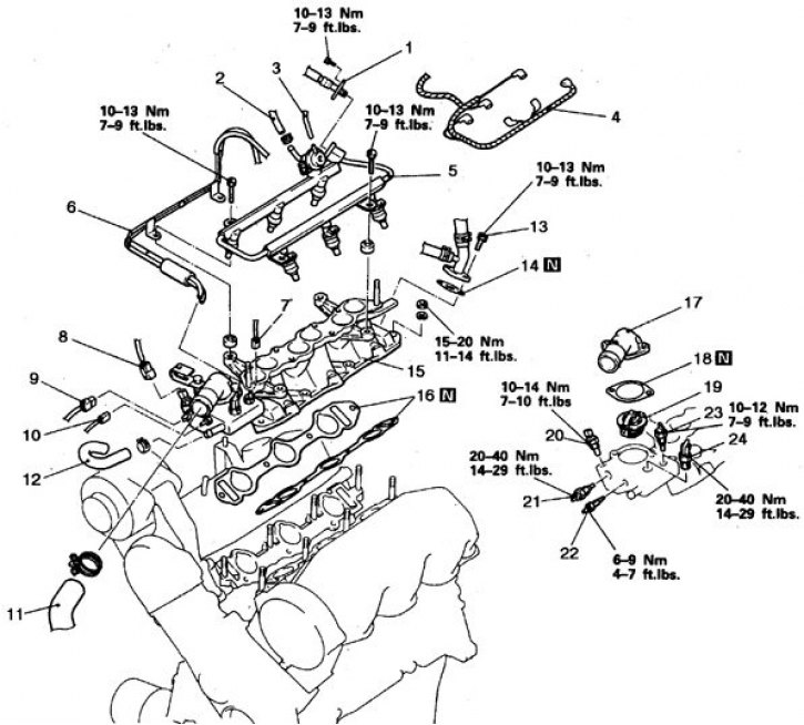
N - parts to be replaced during assembly; 1. High pressure gas pipeline; 2. Return fuel line; 3. Vacuum hose; 4. Engine control wiring connector; 5. Branch pipe, distributor and pressure regulator; 6. Vacuum wiring; 7. Connector for the sensor of the liquid temperature indicator; 8. A/C fluid temperature sensor connector; 9. Socket of the gauge of temperature of a liquid of a control system of the engine; 10. Thermal switch connector; 11. Upper radiator hose; 12. Bypass hose; 13. Bolts for fastening the heater pipe; 14, 16, 18. Gaskets; 15. Collector; 17. Outlet pipe; 19. Thermostat; 20. Air conditioner thermostat; 21. Fluid temperature sensor control system; 22. Thermal switch; 23. Fluid temperature indicator sensor; 24. Thermal valve
Equalization chamber of the engine 3.5 l
1. Lid; 2. Switching block; 3. Vacuum tube A; 4. Vacuum hose A; 5. Receiver; 6. Suction valve solenoid; 7. Bracket; 8. Vacuum tube B; 9. Vacuum hose B; 10. Bracket; 11, 12, 13. Leveling chamber brackets; 14–18. Details of the recycling system (valve, sensor, tube and gaskets); 19. Throttle pipe; 20. Gasket; 22. Leveling chamber; 23. Top section; 24, 25, 26. Gaskets
3.5L Engine Intake Manifold
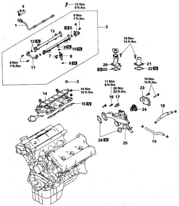
N - parts to be replaced during assembly; 1. Injector wires; 2. Fuel distributor with nozzles; 3, 6. Insulator; 4. Pressure regulator; 5, 9,12. Ring; 7. Bracket; 8. Nozzles; 10. Seal; 11. Petrol pipeline; 14. Fuel distributor; 15. Collector; 16. Fluid temperature indicator sensor; 17. Fluid temperature sensor control system; 18, 19. Hoses; 20–22. outlet pipes; 23. Inlet pipe; 24. Thermostat; 25. Hull; 26. Gasket
Removal and installation
1. Decompress. To do this, disconnect the connector at the rear of the fuel tank, start the engine and, after stopping it, turn off the ignition.
2. Disconnect the battery from the ground. Drain the coolant.
3. Disconnect the air duct.
4. Turn away bolts of adjustment of an accelerator.
5. Label and disconnect all accessible hoses and wires from the manifold.
6. Disconnect the coil wire from the ignition distributor.
7. Remove the coil.
8. Remove throttle tube and set aside (Do not disconnect the cooling system hoses from the nozzle). Note the location of the pipe mounting bolts.
Remove the gasket.
9. Turn away the top bolts of racks, bolts of fastening of an equalizing chamber and remove the chamber and lining.
10. Remove racks.
11. Disconnect both fuel lines and vacuum hoses, remove the fuel distributor. Disconnect the remaining hoses that can be accessed (radiator hose, bypass hose and vacuum wiring).
12. Turn away bolts and remove a chamber of a collector with a laying.
13. Clean the split planes of the manifold and cylinder head chambers. Check the deformation of the planes, if the deviation from the plane exceeds 0.3 mm, then replace the manifold and move all sensors and valves to the new manifold.
14. Installation is carried out in the reverse order. Replace all gaskets (do not apply sealant) and seals. Tighten all connections to the required torque.