



Contents: Compression of springs when…⤓ Additional valve on Mitsubishi…⤓ Removal ⤓ Examination ⤓ Disassembling the valve ⤓ Replacing the oil seal of the…⤓ Valve mechanism assembly ⤓
Compression of springs when installing the valve
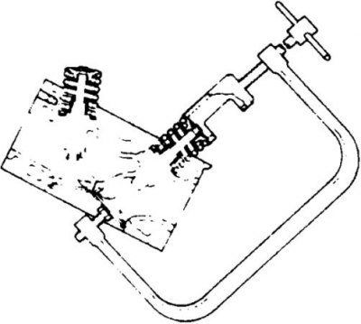
Additional valve on Mitsubishi engines
Early Mitsubishi engines are equipped with an additional valve that closes the jet screwed into the combustion chamber and is designed to form a stream of combustible mixture directed to the spark plug to improve fuel combustion.
When disassembling the cylinder head, these valves must be removed first. For this purpose, the MD 998310 device is used.
When unscrewing the jet valve, the device must not be tilted, as this may bend the rods of the additional valves.
Removal
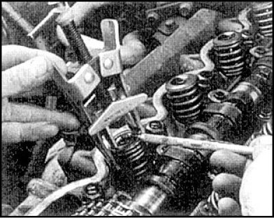
1. When disassembling, compress the first valve spring using a suitable tool and remove the crackers.
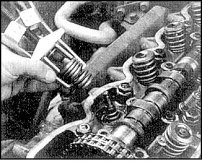
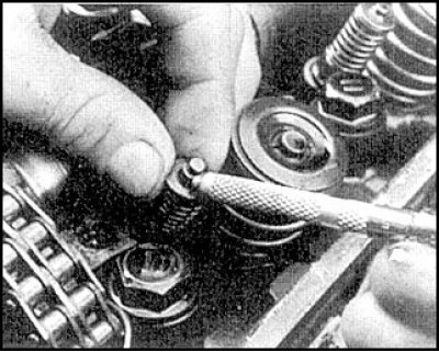
2. Release the valve spring, remove the spring plate, spring and support washer.
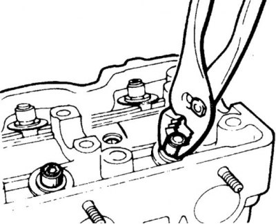
3. Remove the valve and remove the oil seal. Remove carbon deposits from the valves.
Examination
Valve wear check locations
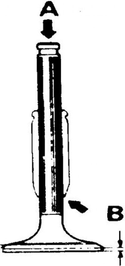
A - places to check valve wear at the end
B – places to check the width of the belt
(The original was published on the website: MitsubishiMan.ru)
Checking the valve stem diameter
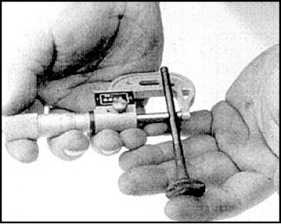
Checking the rod curvature by rolling
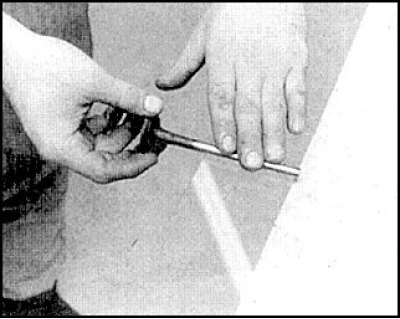
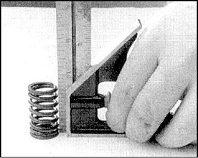
Checking the verticality of the spring
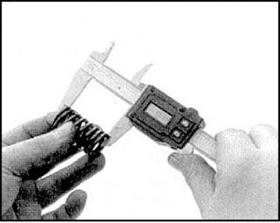
Checking the length of the spring
Valve head belt width and seat belt
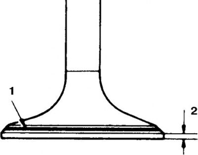
1. Valve head band
2. Landing belt
Carefully inspect the valves, check for cracks on the valve chamfers, traces of uneven wear, metal erosion and burnout. If wear is detected near the entrance to the guide bushing, the ends are oval, and the width of the belt is reduced compared to the norms, replace the valve.
Check the length of the springs and the verticality of the springs (a deviation from the vertical of no more than 2° is allowed). Replace the springs with shrinkage.
Check the valve clearance in the bushings either by the difference in diameter between the stem and the bushing, or by rocking the valve in the bushing. If the gap exceeds the norm, then the valve (or a bushing) replace.
Determine the position and width of the seat by coating the seat with metal based paint and installing the appropriate valve. If the belt is solid, the valve and seat can continue to be used. If the trace is intermittent, then you need to grind the valve and seat and grind the valve to the seat.
Additional jet valve
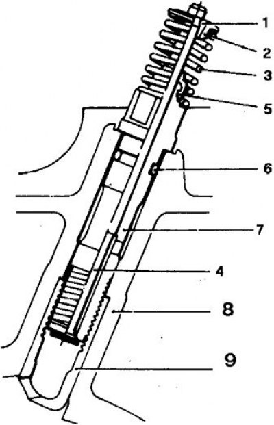
1. Washer; 2. Plate; 3. Spring; 4. Jet; 5. Oil seal; 6. Ring; 7. Body; 8. Cylinder head; 9. Jet nozzle
Disassembling the valve
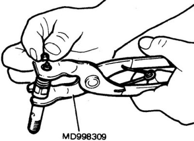
To disassemble the valve, compress the spring, unscrew the nut and remove the crackers. The worn additional valve is replaced as an assembly. To determine its condition, the valve can be disassembled (you will need a device). If the parts are in satisfactory condition, then replace only the valve stem seal.
Replacing the oil seal of the additional valve
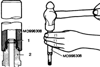
1. Cap
2. Body
After disassembling, check the valve stem for wear; if you find signs of burnout or severe wear, (determined by rolling) replace the valve assembly. Assemble the valve in reverse order.
Additional jet valve before installation
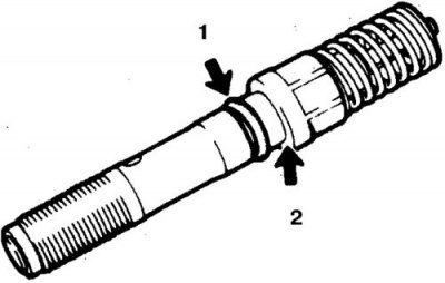
1. New ring
2. Lubricate
When installing, tighten the valve to 18–20 N·m.
Valve mechanism assembly
Pressing on the cap
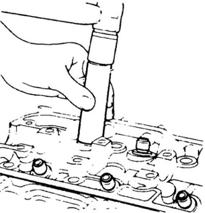
Assembly is carried out in reverse order. Carefully remove any remaining lapping material and rinse. Lubricate the rods and press on new caps. Install all removed parts back in their original places.