



Attention! The head is secured with bolts with internal hexagonal slots. Before removing the head, read the procedure for removing the timing belt and other units.
Engine 2.0 l
Cylinder head of the 2.0L engine
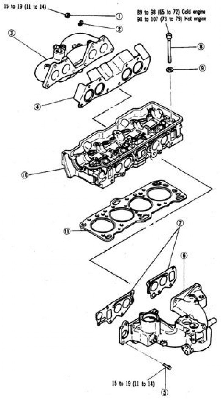
1. Nut (8 pcs.); 2. Washer; 3. Exhaust manifold; 4, 7, 11. Gasket; 5. Bolt (5 pcs.); 6. Intake manifold; 8. Head bolt; 9. Washer (10 pcs.); 10. Cylinder head
Removal and installation
1. Disconnect the battery from ground.
2. Drain the liquid.
3. Remove the carburetor and both manifolds.
4. Remove the radiator.
5. Remove the fan and pulley.
6. Remove the cylinder head cover, mark all disconnected hoses, cables and wires.
7. Remove the top belt cover. Set the piston of the 1st cylinder to TDC of the compression stroke.
8. Loosen the camshaft bolt and, without allowing the crankshaft to rotate or the belt to loosen, remove and place the sprocket on the holder in the lower cover. If necessary, apply a soft pad to maintain tension.
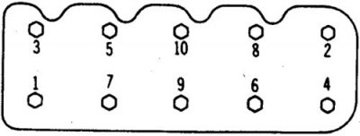
9. In 2–3 steps, unscrew the cylinder head bolts in the order shown.
10. Unscrew the bolts without disturbing the order.
11. Remove the head, if necessary, move it with light blows through a wooden block.
12. Clean the removed head. Perform the necessary work.
13. Installation is carried out in reverse order.
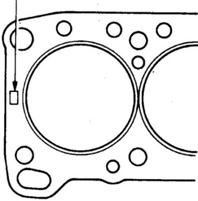
14. Place a new gasket and install the head in one movement (the mark for selecting the cylinder head gasket is indicated by the arrow).
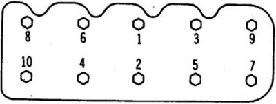
15. Tighten the bolts in the order shown, first by hand, then in 2 stages – first to 46 N·m, then tighten to 92 N·m. Tighten the camshaft bolt to 88 N·m, making sure that the shafts and rocker arms are installed correctly.
2.4L Engine
Cylinder head of the 2.4L engine
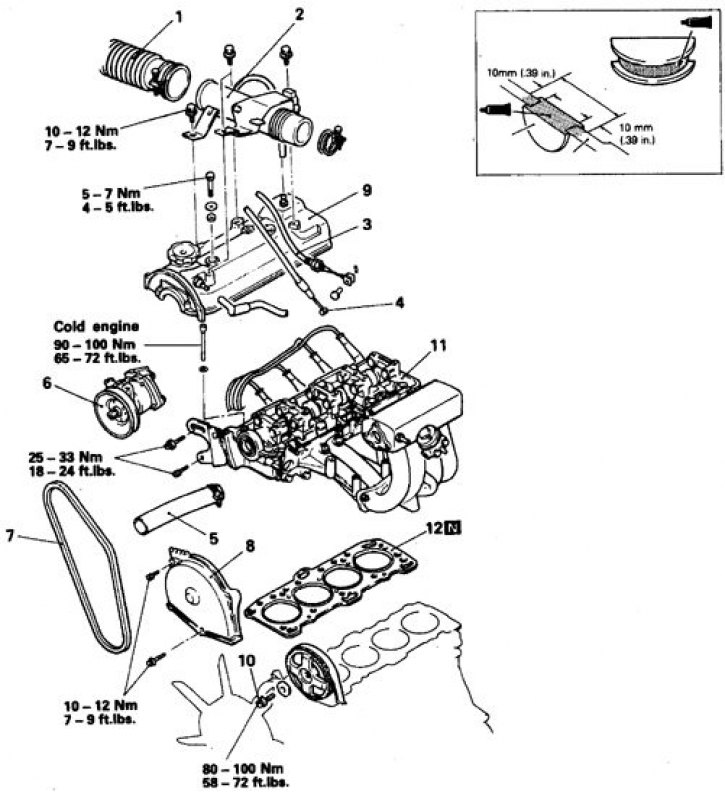
1. Air vent; 2. Branch pipe; 3. Kick-down rope (on a car with automatic transmission); 4. Accelerator cable; 5. Upper radiator hose; 6. Power steering pump; 7. Belt; 8. Upper belt cover; 9. Cylinder head cover; 10. Camshaft sprocket bolt; 11. Cylinder head; 12. Gasket
Loosening and Tightening Procedure for Cylinder Head Bolts (2.4L)
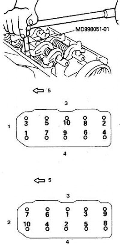
1. Weakening; 2. Tightening; 3. Exhaust valves; 4. Intake; 5. To the belt
Removal and installation
1. Perform decompression. Disconnect the battery from ground.
2. Drain the liquid.
3. Disconnect the upper radiator hose and heater hoses.
4. Remove the air duct and pipe.
5. Disconnect the accelerator cable.
6. Disconnect and plug the fuel hoses, mark all disconnected hoses, cables and wires.
7. Remove the power steering pump and set it aside without disconnecting it from the line.
8. Remove the upper belt cover and cylinder head cover.
9. Align the marks on the camshaft sprocket and on the cylinder head.
10. Loosen the bolt and remove the camshaft sprocket, resting it against the lower cover.
Securely fasten the belt to the sprocket. Rotation of the crankshaft is not allowed.
11. Disconnect the wires from the spark plugs, remove the ignition distributor (subsection 3.4.2).
12. Disconnect the exhaust pipe.
13. Loosen the head bolts in order from the periphery to the center and remove the cylinder head.
14. Remove the manifolds if necessary. Clean the head.
15. Installation is carried out in reverse order. Place a new gasket and install the head. Tighten the bolts in the order shown, first by hand, then in 2 stages – first to 100 Nm. Tighten the camshaft sprocket bolt to 100 Nm.
2.6L Engine
Cylinder Head Bolt Loosening Procedure (2.6L)
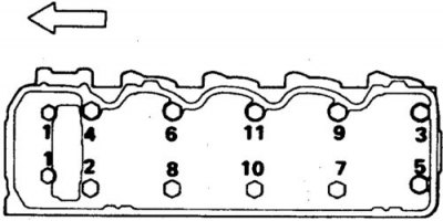
Arrow - to the chain
Removal
1. Disconnect the battery from ground.
2. Drain the liquid.
3. Remove the compressor belt.
4. Remove the shields from the brake master cylinder and exhaust manifold.
5. Remove the air filter.
6. Disconnect the hose from the thermostat.
7. Remove the secondary air filter and pipe.
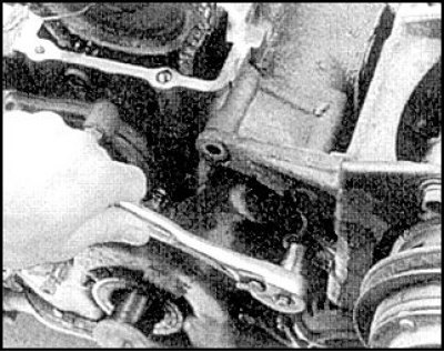
8. Remove any brackets that may interfere with head removal
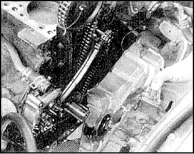
9. Disconnect the hoses and remove the cylinder head cover.
10. Set the piston of the 1st cylinder to TDC of the compression stroke.
11. Disconnect the fuel lines, vacuum hose, and heater hoses. Remove the oil level indicator.
12. Disconnect the high-voltage wires.
13. Disconnect the neutralizer from the exhaust pipe.
14. Label and disconnect the remaining connectors, wires and hoses.
15. Unscrew the camshaft bolt and remove the distributor drive gear.
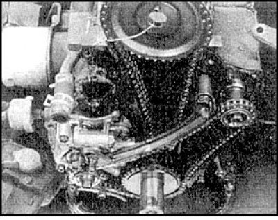
16. Without allowing the crankshaft to rotate or the chain to loosen, remove and place the sprocket with the chain on the holder in the lower cover. If necessary, apply a soft pad to maintain tension.
17. In 2–3 steps, unscrew the cylinder head bolts in the order shown.
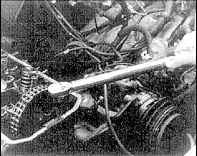 | 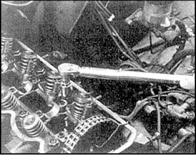 |
18. Before loosening bolt N₂, loosen the 2 front bolts.
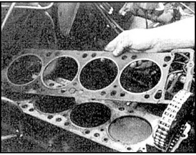
19. Remove the cylinder head gaskets.
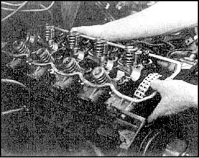
20. Remove the head by lightly tapping it at the corners with a soft hammer. Clean the head.
Installation
1. Installation is carried out in reverse order. Lubricate the joint surface of the chain housing and cylinder block with 3V ART 8660 sealant, preventing the sealant from getting into the oil channels.
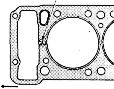
2. Place the new gasket with the mark facing up and install the head.
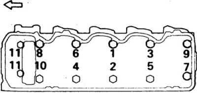
3. Tighten the bolts in the order specified, first by hand, then in 3 stages – first to 27 N·m, then to 61 N·m and finally to 92 N·m. Tighten the 2 front bolts to 19 N·m in 3 stages (5.4, 12 and 19 N·m).
4. Replace all removed gaskets and seals. Tighten the camshaft sprocket bolt to 54 Nm. Install the sprocket. without disturbing the chain tension and without allowing the crankshaft to rotate.
Engine 3.0 and 3.5 l
Attention! To remove and install the camshaft sprocket you will need tools MB 990767-01, MB 998715 or equivalent. The use of other tools is not permitted.
Valve timing components installed on the cylinder head
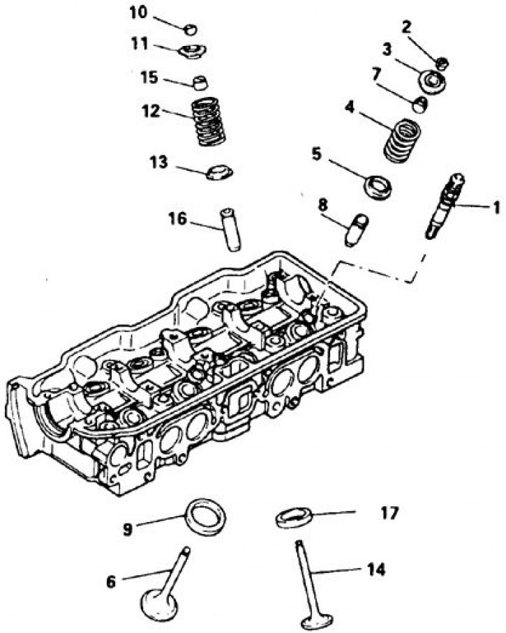
1. Additional combustion chamber jet valve; 2, 10. Rusk; 3, 11. Plate; 4, 12. Spring; 5, 13. Thrust washer; 6, 14. Valve; 7, 15. Cap; 8, 16. Guide bushing; 9, 17. Saddle
Procedure for loosening cylinder head bolts (3.0 and 3.5 l)
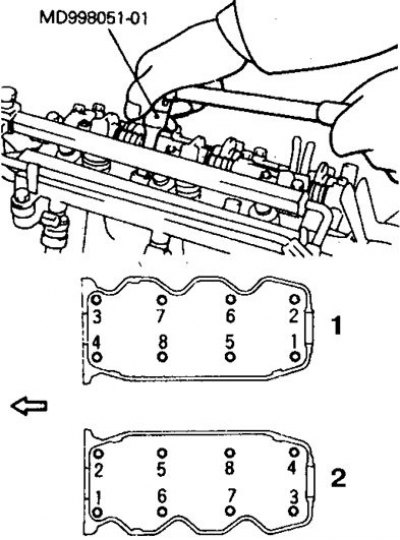
1. Right head
2. Left head
Cylinder Head Bolt Tightening Sequence (3.0 and 3.5 l)
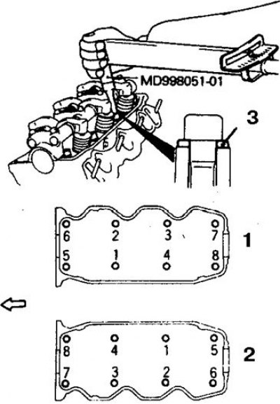
1. Right head
2. Left head
3. Washer
Removal and installation
1. Decompress the fuel system.
2. Disconnect the battery from ground.
3. Drain the coolant and disconnect the upper radiator hose.
4. Remove the air duct, drive belts, fan and pulleys.
5. Remove the compressor and power steering pump, set them aside without disconnecting them from the lines.
6. On the right cylinder head, disconnect the wiring and remove the generator and bracket. Remove the oil level indicator.
7. Remove the timing belt covers.
8. Set the piston of the 1st cylinder to TDC of the compression stroke, loosen the tensioner bolt and mark the direction of rotation on the belt, remove the toothed belt. Rotation of the crankshaft is not allowed.
9. Disconnect the high-voltage wires.
10. When dismantling the left cylinder head, remove the ignition distributor (see subsection 3.4.2).
11. Remove the cylinder head cover.
12. Remove both manifolds (see subsection 3.4.15 and subsection 3.4.16).
13. Loosen the bolts and remove the cylinder head. If necessary, first remove the camshaft sprocket, generator bracket and rear belt cover.
14. Installation is carried out in reverse order. Place the new gasket with the mark facing up and install the head. Tighten the bolts in the order shown, first by hand and then in 3 stages to 90–10 N·m. (until 1991.) or 103–113 Nm. (1992-98).
Install the timing belt following the description above.