



Contents: Engine chain 2.6L ⤓ Timing marks for the chain on a 2.6L…⤓ Combination of sprockets and small…⤓ Removal ⤓ Installation ⤓
Engine chain 2.6L
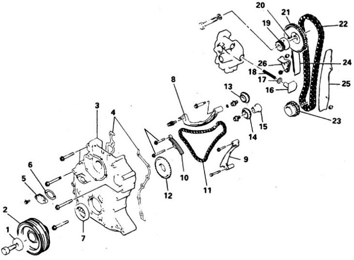
1. Washer; 2. Pulley; 3. Chain cover; 4, 6. Gasket; 5. Plug; 7. Seal; 8. Calmator B; 9. Calm A; 10. Calm C; 11. Small chain; 12. Asterisk B; 13. Oil pump sprocket; 14. Left roller sprocket; 15. Bushing; 16. Tensioner; 17. Seal; 18. Spring; 19. Gear; 20. Pin; 21. Camshaft sprocket; 22. Camshaft chain; 23. Crankshaft sprocket; 24. Chain tensioner damper; 25. Chain tensioner damper; 26. Sprocket holder
Timing marks for the chain on a 2.6L engine
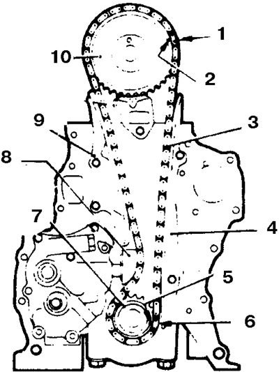
1, 6. Anodized link; 2, 5. Mark (hole); 3. Chain; 4, 9. Calmator; 7. Crankshaft sprocket; 8. Tensioner; 10. Camshaft sprocket
Combination of sprockets and small chain (2.6L)
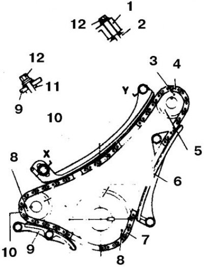
1, 6, 9. Calmator; 2. Cylinder block; 3, 8. Label; 4, 7. Anodized link; 5. Asterisk; 10. Section along X; 11. Section along Y; 12. Bolt
Removal
1. Disconnect the battery from ground.
2. Drain the liquid.
3. Disconnect the radiator hose and remove the upper fan shroud.
4. Remove the fan with the coupling and store it without disturbing its working position.
5. Remove the accessory belts.
6. Remove the fan pulley from the cooling pump.
7. Disconnect the heater hose from the cooling pump.
8. Loosen the bolts, paying attention to their location, and remove the cooling pump.
9. Loosen the bolt and use a puller to press off the crankshaft pulley.
Original source of information www.MitsubishiMan.ru
10. Remove the cylinder head cover.
11. Remove the 2 front chain cover mounting bolts from the cylinder head.
12. Remove the pan mounting bolts screwed into the chain cover.
13. Loosen the bolts and remove the cover, breaking the seal with a sharp tool.
If the front part of the oil pan gasket was damaged when removing the cover, carefully cut this part flush with the cylinder block.
14. Replace the front oil seal by carefully removing it and pressing in a new one using the MD998376–01 or MB990938–01 tool.
15. Set the piston of the 1st cylinder to TDC of the compression stroke (the rocker arms should swing freely within the clearance).
16. Remove the 3 dampers that rest against the vibration damper roller chain, marking each of the mounting bolts.
17. Remove the small chain from the vibration damper shaft and from the oil pump. If the chain does not give in, then unscrew the bolts and remove the sprockets together with the chain. Remove the keys (if provided). Please note the orientation of the stars.
18. Remove the 1st crankshaft sprocket.
19. Secure the tensioner plunger to the oil pump housing with wire.
20. Loosen the bolt and remove the camshaft sprocket and distributor drive gear. You can also remove the chain together with the crankshaft and camshaft sprockets.
21. Remove the dampers, keep all bolts and washers in the same order.
Installation
1. Check the condition of the chain; if worn links are found, replace the chain.
Replace the worn tensioner plunger along with the seal and spring.
Replace the dampers if they have developed deep grooves. If the teeth are visibly worn, replace the sprockets
2. Install the left and right dampers.
3. Place the chain on the crankshaft and camshaft sprockets, aligning the marks with the anodized chain links. Place the sprocket on the crankshaft and secure the camshaft sprocket to the holder.
4. Install the camshaft sprocket by passing the pin through the hole and tighten the bolt to 54 N·m.
5. Remove the wire from the tensioner and tighten the chain.
6. Put the small chain on together with the sprockets, aligning the marks and the links with distinctive coloring (install the stars without disturbing their previous position).
7. Put on gear B.
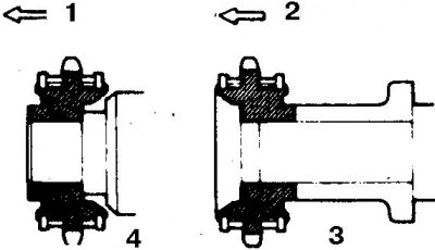
8. Place the small chain on the crankshaft sprocket, aligning the anodized link with mark 3.
Place the remaining sprockets on the shaft and oil pump, slightly tighten the bolts (1, 2 – to the chain; 3 – installing the sprocket on the left roller; 4 – installing the sprocket on the journal of the oil pump drive gear).
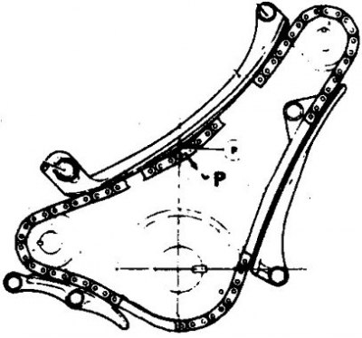
9. Turn both small chain and oil pump sprockets, set the location of greatest slack to point P in the illustration.
10. Install the small chain guides and adjust the upper guide (B) so that the gap between the chain and the guide is 0.2–0.8 mm. Tighten the bolt to a torque of 19 N·m.
11. Install all removed parts. When installing the covers, check the condition of the gaskets. Cut out the part of the removed gasket and install it, lubricating the joint with sealant. Tighten the chain cover bolts to 14 N·m, the crankshaft bolt to 119 N·m, the oil pan bolts to 5 N·m, and the front cylinder head bolts to 19 N·m. After starting the engine, listen for noise from the chain. If unusual noises are heard, stop the engine and check the installation and tension of the chain. When finished, adjust the drive belts of the attachments.