



Removal
To remove the cylinder head gasket, perform the following operations in sequence.
1. Drain the coolant from the engine cooling system.
2. Remove the inlet hose and air filter.
3. Remove the exhaust pipe.
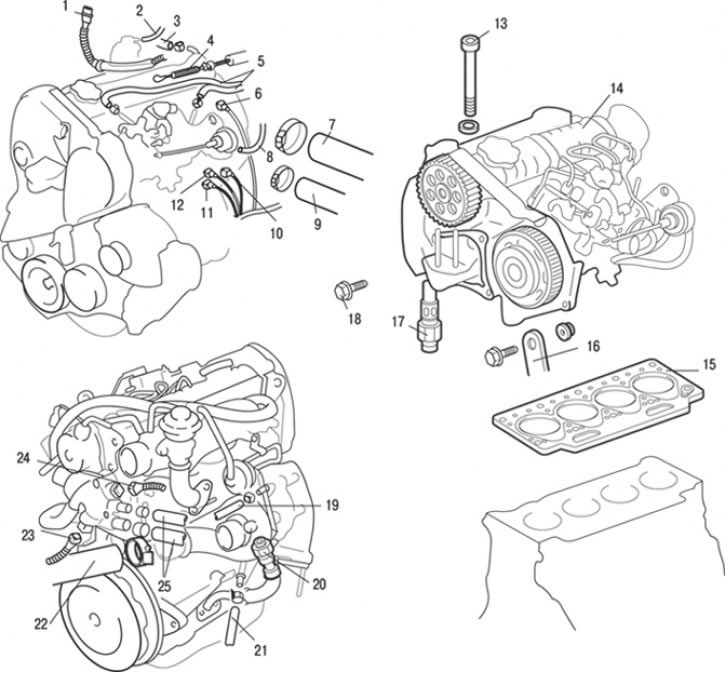
Fig. 4.26. Cylinder head gasket: 1 – glow plug relay connector; 2 – connection of vacuum hoses; 3 – brake booster hose connection; 4 – fuel injection pump control cable connection; 5 – fuel hose connections; 6 – connector of the injector needle lift sensor; 7 – connection of the upper radiator hose; 8 – connection of vacuum hoses; 9 – Cooling system hose connection; 10 – immobilizer connector; 11 – load lever sensor connector; 12 – Fuel metering solenoid valve connector; 13 – cylinder head mounting bolt; 14 – cylinder head assembly; 15 – cylinder head gasket;16 – turbocharger support bracket connection; 17 – oil pipe assembly connection, 30 Nm; 18 – timing belt lower cover mounting bolt, 20 Nm; 19 – Cooling system hose connections; 20 – oil return pipe connection, 25 Nm; 21 – Cooling system hose connections; 22 – connection of inlet hose A; 23 – coolant temperature sensor connector (to the temperature gauge); 24 – coolant temperature sensor connector; 25 – heater hose connections
4. Disconnect vacuum hoses 2 (Fig. 4.26).
5. Loosen the clamp and disconnect the brake booster hose 3.
6. Disconnect the connectors of the load lever sensor 11, the fuel metering electromagnetic valve 12, the immobilizer 10, the injector needle lift sensor 6 and the glow plug relay 1.
7. Disconnect the fuel injection pump control cable 4.
8. Loosen the clamps and disconnect the fuel hoses 5.
9. Loosen the clamp and disconnect the upper radiator hose 7.
10. Loosen the clamp and disconnect the cooling system hose 9.
11. Disconnect the connectors of the coolant temperature sensor (on the temperature gauge) 23 and the coolant temperature sensor 24.
12. Loosen the clamps and disconnect the heater hoses 25.
13. Loosen the clamps and disconnect the cooling system hoses 21.
14. Unscrew and disconnect the oil return pipes 20.
15. Loosen the clamp and disconnect the inlet hose A 22.
16. Unscrew and disconnect the oil pipe 17 as an assembly.
17. Unscrew the nut, remove the bolt and separate the turbocharger support bracket 16.
18. Remove the timing belt.
19. Unscrew bolt 18 securing the lower timing belt cover.
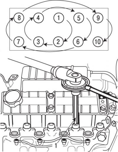
Fig. 4.27. Sequence of tightening the cylinder head bolts: 1 – key for tightening bolts to the required angle (MB991614)
20. Loosen the cylinder head mounting bolts in 2 or 3 stages in the reverse order to that shown in Fig. 4.27, and then remove the cylinder head assembly.
21. Carefully remove head 14 (see Fig. 4.26) of the cylinder block as an assembly.
22. Remove cylinder head gasket 15.
Preparing for installation
1. The mating surfaces of the cylinder head and block must be completely clean. Use a hard plastic or wooden scraper to clean them. Be careful when cleaning, as the aluminum alloy is very easy to damage. Check that carbon deposits do not get into the oil and water passages. This is especially important for the lubrication system, as carbon deposits can block the oil supply to the engine components. Clean the passages if necessary.
2. Check the mating surfaces of the cylinder head and block for nicks, deep scratches and other damage. If the defects are small, they can be removed by mechanical treatment. However, if the defects are significant, the parts must be replaced.
3. Using a metal ruler and feeler gauge, check the flatness of the mating surfaces.
4. Clean the bolt holes in the block. Driving a bolt into an oil-filled hole can cause the block to burst due to hydraulic pressure.
Installation
Installation is carried out in the reverse order of removal, taking into account the following.
1. Degrease the mating surfaces of the gasket.
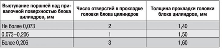
2. Select a cylinder head gasket of the required thickness in accordance with the amount of piston protrusion above the mating surface of the cylinder block. The nomenclature of cylinder head gaskets is given in Table 4.1. The thickness of the cylinder head gasket is determined by the number of holes on the edge of the gasket. Measure the amount of piston protrusion above the mating surface of the cylinder block, calculate the average value. Then, according to Table 4.2, select a cylinder head gasket of the required thickness.
If it is necessary to replace the cylinder head gasket, determine the type of gasket and select one that is the same in shape and number of holes in it.
Table 4.1. Cylinder number on which the check/adjustment is carried out depending on the cylinder number with equally open intake and exhaust valves
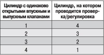
Table 4.2. Cylinder head gasket thickness
Caution! When replacing a piston or connecting rod, always measure the piston protrusion above the cylinder block mating surface, as it may change during such operations.
3. Turn the crankshaft so that the piston of the 1st cylinder travels approximately a quarter of the way past TDC.
4. Position the cylinder head so that the cylinder block locating pins fit into the recesses in the cylinder head.
5. Before installing the bolts, check the length of the bolt shaft (to the head), which should be at least 120.5 mm. If the length of at least one of the bolts is greater, all cylinder head mounting bolts must be replaced.
6. Install the washers.
7. Before installation, lubricate the threaded parts of the bolts and the surfaces of the washers with a small amount of engine oil.
8. Tighten the cylinder head bolts in 7 stages in the sequence shown in Fig. 4.27.
Bolt tightening steps:
- 1st – tighten to 30 Nm;
- 2nd – tighten to an angle of 50° ±4°;
- 3rd - wait at least 3 minutes;
- 4th - completely loosen all bolts in reverse order;
- 5th – tighten to 25 Nm.
- 6th – tighten all bolts to an angle of 213° ±2°.
- 7th – after warming up the engine, wait until it cools down completely, and then tighten the bolts to an angle of 120° ±2°.
9. Install the intake pipe of the exhaust system.
10. Adjust the fuel injection pump control cable.
11. Install the inlet hose and air filter.
12. Fill the cooling system with coolant.
13. Remove air from the fuel system.