



Contents: Removal and installation ⤓ Examination ⤓
Removal and installation
Before you begin removing parts, perform the following operations:
- a) (GDI engines) Remove the engine cover.
- b) Remove the engine crankcase protective cover.
The parts are removed in the order of numbers shown in the figure "Removing the exhaust manifold".
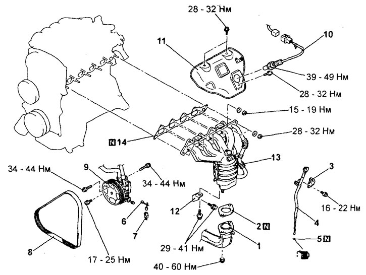
Removal the exhaust manifold (4G15-GDI engine). 1 - exhaust pipe, 2 - exhaust pipe gasket, 3 - engine mount bracket, 4 - engine oil level guide tube and dipstick assembly, 5 - O-ring gasket, 6 - power steering fluid pressure switch connector, 7 - air conditioning compressor electromagnetic clutch connector, 8 - air conditioning compressor and power steering pump drive belt, 9 - power steering pump and adjusting bar assembly, 10 - oxygen sensor, 11 - heat shield, 12 - exhaust manifold bracket, 13 - exhaust manifold, 14 - exhaust manifold gasket.
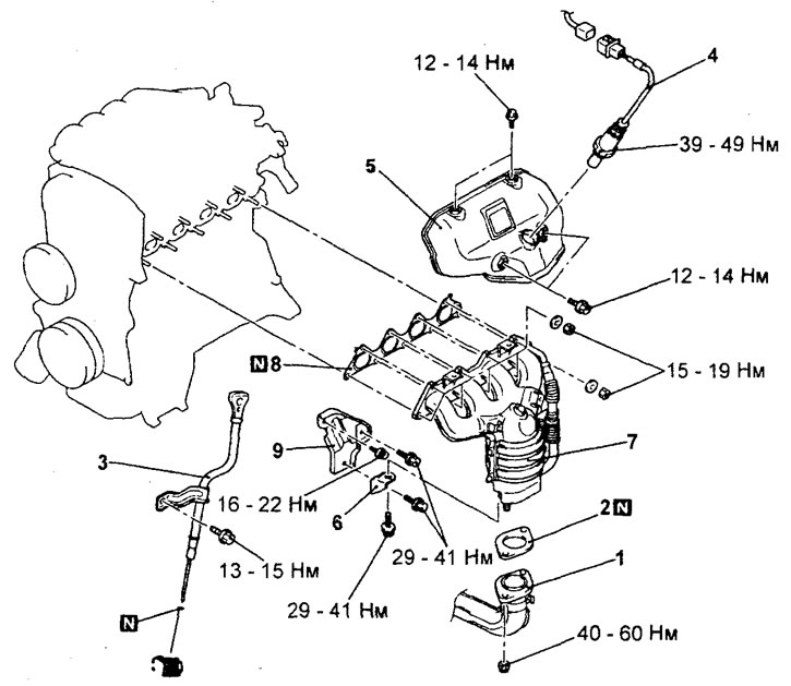
Removal the exhaust manifold (4G93-GDI engine). 1 - exhaust pipe, 2 - exhaust pipe gasket, 3 - engine oil level guide tube and dipstick assembly, 4 - oxygen sensor, 5 - heat shield, 6 - exhaust manifold bracket "B", 7 - exhaust manifold, 8 - exhaust manifold gasket, 9 - exhaust manifold bracket "A".
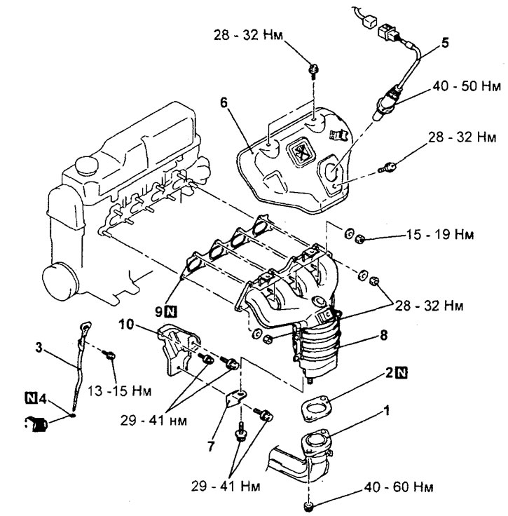
Removal the exhaust manifold (4G15-MPI engine). 1 - exhaust pipe, 2 - exhaust pipe gasket, 3 - engine oil level guide tube and dipstick assembly, 4 - O-ring gasket, 5 - oxygen sensor, 6 - heat shield, 7 - exhaust manifold bracket "B", 8 - exhaust manifold, 9 - exhaust manifold gasket, 10 - exhaust manifold bracket "A".
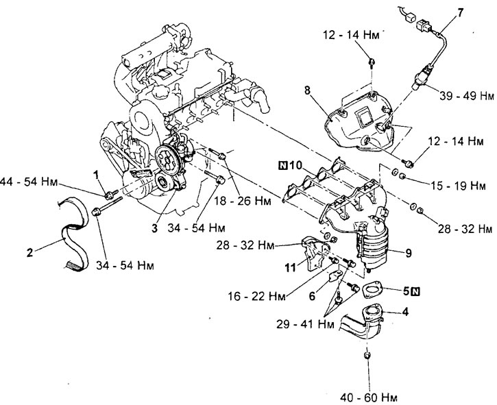
Removal the exhaust manifold (4G93-MPI engine).1 - power steering pump strut mounting bolt, 2 - air conditioning compressor and power steering pump drive belt, 3 - tensioner bracket and power steering pump assembly, 4 - exhaust manifold inlet pipe, 5 - exhaust manifold inlet pipe gasket, 6 - exhaust manifold bracket "B", 7 - oxygen sensor, 8 heat shield, 9 - exhaust manifold, 10 - exhaust manifold gasket, 11 - exhaust manifold bracket "A".
When removing parts, pay attention to the operation
1. (4G15-GDI engine) Removing the power steering pump drive belt.
a) Loosen bolts "A", "B" and "C" of the power steering pump.
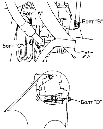
b) Loosen the adjusting bolt "D" to release the belt tension, then remove the belt.
Caution: If the air conditioning compressor and power steering pump drive belt is reused, an arrow indicating the direction of rotation (clockwise) must be chalked on the reverse (non-working) surface of the belt.
2. (4G15-GDI engine) Removing the power steering pump and adjusting bar assembly.
Remove the power steering pump and adjuster bar assembly with the hoses connected.
Note: After removal, secure the power steering pump and hoses with wire in a place where it will not be in the way or damaged.
3. (4G93-MPI Engine) Removing the tensioner bracket and power steering pump assembly.
Remove the tensioner bracket and power steering pump assembly with the hoses connected.
Note: After removal, secure the power steering pump and hoses with wire in a place where it will not be in the way or damaged.
4. Removing the oxygen sensor.
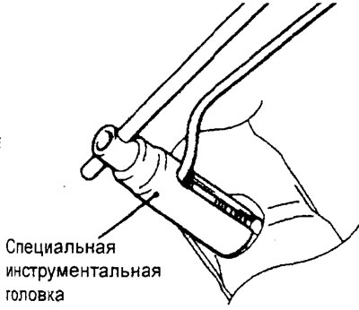
To avoid damaging the sensor wiring, use a special tool head to remove it.
− Installation of parts is carried out in the reverse order of removal.
When installing the parts, pay attention to the oxygen sensor installation operation.
To avoid damaging the sensor wiring, use a special tool head to install it.
- After completing the installation of the parts, perform the following operations:
- a) Install the engine crankcase protective cover.
- b) (GDI engines) Install the engine cover.
Examination
1. Check the exhaust manifold and heat shield for damage.
2. Check for exhaust gas leaks from the exhaust manifold (due to burnout) and connections to the exhaust system inlet pipe.
3. Using a straightedge and a set of feeler gauges, measure the non-flatness of the mating surface of the cylinder head, as well as the mating surface of the exhaust manifold.
Non-flatness of the mating surface:
- Nominal - 0.15 mm or less
- Maximum permissible - 0.20 mm
4. If defects are found during inspection according to the above points, the part is subject to replacement.