
English Русский
Български
Беларускі
Український
Српски
Hrvatski
Română
Polski
Slovenský
Magyar
Articles Bookmark Contacts Sitemap   
Company Audi Company Ford Company Hyundai Company Kia Company Mazda Company Mercedes-Benz Company Nissan
MitsubishiMan.ru


Home Colt Lancer Galant L200 Outlander Pajero Others
L200 4 (2005-2014, diesel)

Removal and installation of fuel supply system components (Mitsubishi L200 4)

  • Home
  • L200
  • 4 (2005-2014, diesel)
  • Power unit
  • Fuel system
  • Removal and installation of fuel supply system components
0
Contents: Fuel filter removal sequence for…⤓ Sequence of removing the glow plug…⤓ Sequence of removing the fuel line…⤓ Sequence of removal of the return…⤓ Fuel filter removal sequence for…⤓ Sequence of removing the glow plug…⤓ Sequence of removing the fuel line…⤓
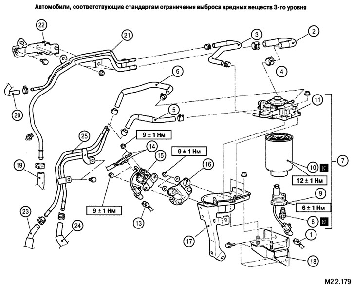

Fuel filter removal sequence for Tier 3 emission control vehicles (see Fig. M2 2.179)


1. Water level sensor connector.

2. Fuel line B.

3. Fuel line C.

5. Return fuel line B (for vehicles with fuel line heater).

6. Return fuel line C (for vehicles with fuel line heater).

7. Fuel filter assembly.

8. Drain plug with sealing ring.

9. Water level sensor in the filter.

10. Filter element.

11. Manual fuel filter priming pump.

Sequence of removing the glow plug relay


13. Glow plug relay connector.

14. Glow plug relay contacts.

15. Glow plug relay.

16. Glow plug relay bracket.

Sequence of removing the fuel line bracket


1. Water level sensor connector.

2. Toplgoopkhovd V.

3. Fuel-sucking S.

5. Return fuel line B (for vehicles with fuel line heater).

6. Return fuel line C (for vehicles with fuel line heater).


7. Fuel filter assembly.

13. Glow plug relay connector.

14. Glow plug relay contacts.

17. Fuel filter protection.

18. Fuel filter bracket.

19. Fuel line connection A.

20. Fuel line connection D.

21. Fuel pipe.

22. Fuel pipe bracket.

Sequence of removal of the return fuel line (for cars with a fuel return line heater)


5. Return fuel line B (for vehicles with heater.

6. Return fuel line C (for vehicles with fuel line heater).

(The material was borrowed from the website: MITSUBISHIMAN.ru)

24. Return fuel line D (for vehicles with fuel line heater).

25. Return fuel line assembly (for vehicles with fuel line heater).
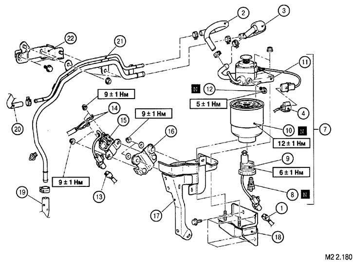


Fuel filter removal sequence for Tier 4 emission control vehicles (see Fig. M2 2.180)


1. Water level sensor connector.

2. Fuel line B.

3. Fuel line C.

4. Fuel line heater connector (for vehicles operated in cold climates).

7. Fuel filter assembly.

8. Drain plug with sealing ring.

9. Water level sensor in the filter.

10. Filter element.

11. Manual fuel filter priming pump.

Sequence of removing the glow plug relay


13. Glow plug relay connector.

14. Glow plug relay contacts.

15. Glow plug relay.

16. Glow plug relay bracket.


Sequence of removing the fuel line bracket


1. Water level sensor connector.

2. Fuel line B.

3. Fuel line C.

4. Fuel line heater connector (for vehicles operated in cold climates).

7. Fuel filter assembly.

13. Glow plug relay connector.

14. Glow plug relay contacts.

17. Fuel filter protection.

18. Fuel filter bracket.

19. Fuel line connection A.

20. Fuel line connection D.

21. Fuel pipe.

22. Fuel pipe bracket.
This article is available at: russian, bulgarian, belarusian, ukrainian, serbian, croatian, romanian, polish, slovak, hungarian
This article was reviewed by: Nikita Romanov
Share with friends:
◀ Previous
L200 4: Fuel system
Next ▶

Disassembly and assembly of the fuel tank measuring and receiving unit
Removal and installation the fuel tank
Fuel supply system — design description
Replacing the fuel filter element
Glow plugs
Similar materials for other Mitsubishi models

➤ Components of the fuel injection system Mitsubishi Colt 4 and 5 (1991-2003)
➤ Checking the fuel injection system components (MPI) Mitsubishi Lancer 9 (2000-2007, petrol)
➤ Checking the condition of the fuel evaporative emission… Mitsubishi Galant 6 and 7 (1987-1998)
➤ General information about the fuel supply and injection… Mitsubishi Outlander 1 (2003-2008)
➤ Locations of power supply system components and assemblies Mitsubishi Pajero 1 and 2 (1982-1999)
➤ Bleeding the fuel system (diesel engines only) Mitsubishi Carisma (1995-2004)
Link in different formats to this article
Comments and feedback from visitors
No comments yet


Add up two numbers 34 + 15


L200 4 (2005-2014, diesel) 
  • General information
  • User manual
  • Maintenance
  • Power unit
  • Diesel engine
  • Lubrication system
  • Fuel system
  • Control system
  • Transmission
  • Clutch
  • Mechanical gearbox
  • Transfer case
  • Front axle
  • Rear axle
  • Chassis and running gear
  • Car suspension
  • Steering
  • Brake system
  • Body and interior
  • Exterior (external elements)
  • Interior (internal elements)
  • Doors, locks and windows
  • Electrical equipment
  • Equipment and devices
  • Electrical circuits
MitsubishiMan.ru © 2018–2026 • Mobile version • Articles about Mitsubishi • Contacts • Sitemap: EN BG BY UA RS HR RO PL SK HU • Site search • Bookmark
Colt 2 and 3 (1983-1993) · Colt 4 and 5 (1991-2003) · Colt 5 (1995-2003) · Lancer 3 and 5 (1984-1992) · Lancer 9 (2000-2007) · Galant 5 (1983-1989) · Galant 6 and 7 (1987-1998) · L200 4 (2005-2014) · Outlander 1 (2003-2008) · Pajero 1 and 2 (1982-1999) · Pajero 4 (2006-2021) · Carisma (1995-2004) · Space Star (1998-2005) ·
This resource sets cookies 🍪 to avoid bothering you with repeated data entry.