Caution: EGR Solenoid Valve Test Procedures (OG) and the canister purge solenoid valve are given in the relevant section of the chapter "Emission control system".
Injection system main relay
1. Make sure there is a closed circuit between the terminals "2" And "3".
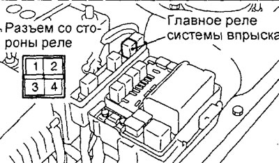
2. Make sure there is no short circuit between the terminals "1" And "4".
3. Connect the negative battery cable to the terminal "2" relay connector, and the positive terminal wire to the output "3", then check that the circuit is closed between the terminals "1" And "4" when powered by a battery.
4. In case of detection of malfunctions when checking circuits point by point "2" - "3" replace the main relay of the injection system.
Fuel pump relay
1. Make sure there is a closed circuit between the terminals "1" And "4".
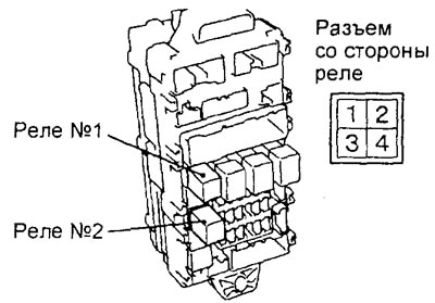
2. Make sure there is no short circuit between the terminals "2" And "3".
3. Connect the negative battery cable to the terminal "4" relay connector, and the positive terminal wire to the output "1", then check that the circuit is closed between the terminals "2" And "3" when powered by a battery.
4. In case of detection of malfunctions when checking circuits point by point "2" -"3" replace the fuel pump relay.
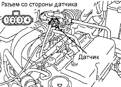
Intake manifold air temperature sensor (4G 15 engine)
Note: The intake manifold air temperature sensor is built into the intake manifold absolute pressure sensor, so the air temperature indicated by the sensor will differ from the ambient temperature depending on the condition of the engine.
1. Disconnect the intake manifold air temperature sensor connector.
2. Measure the resistance between the terminals of the connector "1" And "3".
Table. Rated values.
| Temperature | Resistance |
| -20°C | 13.0 -17.0 kOhm |
| 0°C | 5.3 - 6.7 kOhm |
| 20°C | 2.3 - 3.0 kOhm |
| 40°C | 1.0 -1.5 kOhm |
| 60°С | 0.56 - 0.76 kOhm |
| 80°С | 0.30 - 0.42 kOhm |
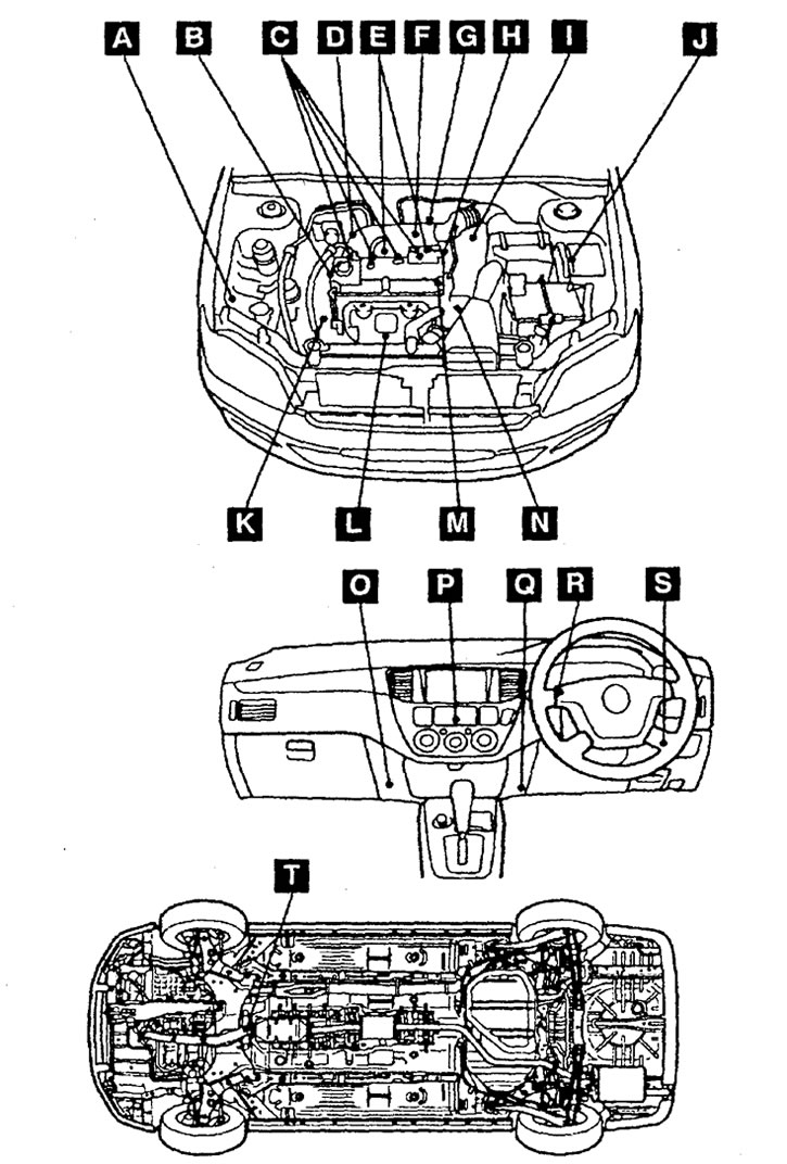
Location of fuel injection system components (4G15 engine). A - refrigerant pressure sensor (automatic air conditioner), B - sensor-switch for fluid pressure in the power steering hydraulic system, C - injectors, D - knock sensor, E - ignition coil (power transistor), F - absolute pressure sensor in the intake manifold (with integrated intake manifold air temperature sensor), G - throttle position sensor, H - idle speed control servo (stepper motor), I - start inhibit switch (at the checkpoint), J - main injection system relay and air conditioning compressor electromagnetic clutch relay, K - crankshaft position sensor, L - oxygen sensor (front), M - camshaft position sensor, N - coolant temperature sensor, O - electronic engine and CVT control unit, P - air conditioning switch, Q - diagnostic connector, R - indicator "CHECK ENGINE", S - relay (#1 and #2) fuel pump, T - oxygen sensor (rear).
3. Remove the air temperature sensor in the intake manifold.
4. Measure the resistance by heating the sensor with a hair dryer. As the temperature rises, the resistance should decrease.
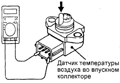
5. If the resistance is out of specification or does not change, replace the intake manifold air temperature sensor.
6. Install the air temperature sensor in the intake manifold, tighten the sensor mounting screws with the nominal tightening torque.
Tightening torque - 4- 6 N.m
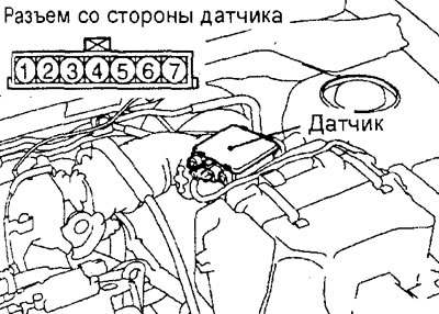
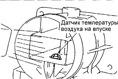
Intake air temperature sensor (4G93 engine)
Note: The intake air temperature sensor is built into the mass air flow sensor, so the air temperature indicated by the sensor will differ from the ambient temperature, depending on the condition of the engine.
1. Disconnect the mass air flow sensor connector.
2. Measure the resistance between the terminals of the connector "5" And "6".
Table. Rated values.
| Temperature | Resistance |
| -20°C | 13.0-17.0 kOhm |
| 0°С | 5.3 - 6.7 kOhm |
| 20°C | 2.3 - 3.0 kOhm |
| 40°C | 1.0 - 1.5 kOhm |
| 60°C | 0.56 - 0.76 kOhm |
| 80°С | 0.30 - 0.42 kOhm |
3. Measure the resistance by heating the sensor with a hair dryer. As the temperature rises, the resistance should decrease.
4. If resistance does not correspond to nominal or does not change replace the gauge of the mass expense of air.
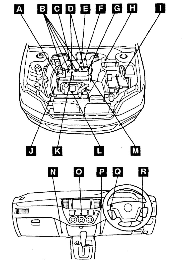
Location of fuel injection system components (4G93 engine). A - sensor-switch for fluid pressure in the power steering hydraulic system, B - injectors, C - canister purge solenoid valve, D - ignition coil (power transistor), E - EGR valve servomotor, F - Throttle position sensor, G - Idle speed control servo (stepper motor), H - mass air flow sensor (with integrated intake air temperature sensor and barometric pressure sensor), I - injection system main relay, air conditioning compressor electromagnetic clutch relay and electric fan control relay, J - crankshaft position sensor, K - knock sensor, L - oxygen sensor, M - camshaft position sensor and coolant temperature sensor, N - electronic engine and automatic transmission control unit, O - air conditioner switch, P - diagnostic connector, Q - indicator "CHECK ENGINE", R - fuel pump relay (#1 and #2).
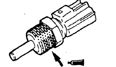
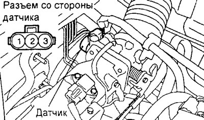
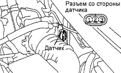
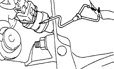
Coolant temperature sensor
1. Remove the coolant temperature sensor.
Attention: when removing and installing the sensor, do not touch the tool to its connector (plastic part).
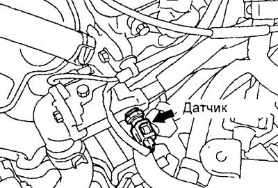
Engine 4G15.
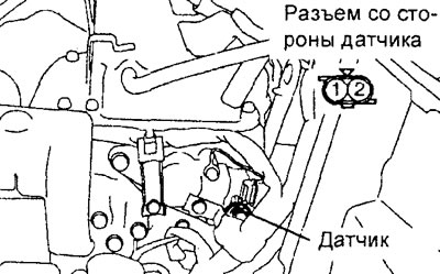
Engine 4G93.
2. Measure the resistance between the sensor leads by immersing its sensing element in heated water.
Table. Rated values.
| Temperature | Resistance |
| -20°C | 14.00 - 17.00 kΩ |
| 0°C | 5.10 - 6.50 kOhm |
| 20°C | 2.10-2.70 kOhm |
| 40°C | 0.90 - 1.30 kOhm |
| 60°C | 0.48 - 0.68 kOhm |
| 80°С | 0.26 -0.36 kOhm |
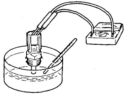
3. If the measured resistance differs significantly from the nominal value, then replace the engine coolant temperature sensor.
4. Reinstall the engine coolant temperature sensor by applying sealant to the sensor threads. Tighten the sensor to the specified torque.
Sealant - 3M NUT Locking Part #4171 or equivalent
Tightening torque - 19 - 39 N.m
Throttle position sensor
1. Disconnect the throttle position sensor connector.
Engine 4G15.
Engine 4G93.
2. Measure the resistance between the leads "2" And "3" sensor connector.
Rated resistance:
- Engine 4G15 - 3.5-6.5 kOhm
- Engine 4G93 - 2.0 - 4.0 kOhm
3. Measure the resistance between the indicated sensor connector pins by slowly opening the throttle from the fully closed position (idling) to the fully open position.
Sensor connector pins:
- Engine 4G15 - "1" And "3"
- Engine 4G93 - "1" And "2"
4. The resistance should change smoothly in proportion to the throttle opening angle. If the resistance differs from the nominal value, or does not change smoothly, then replace the throttle position sensor.
Note: after replacing the sensor, it must be adjusted.
5. Connect the throttle position sensor connector.
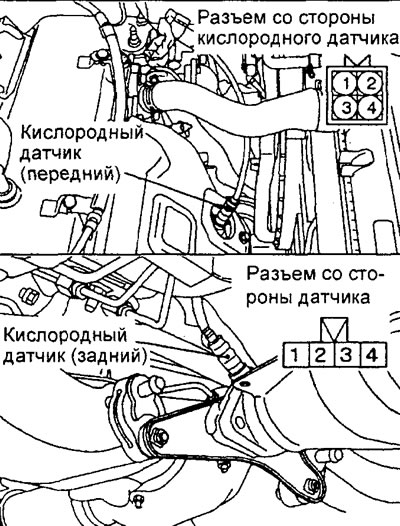
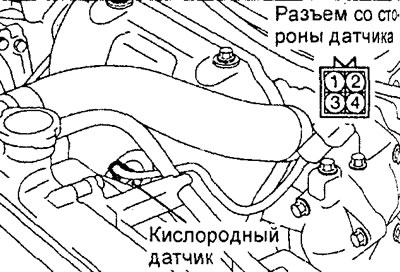
Oxygen sensor
Note:
- - Two oxygen sensors were installed on the 4G15 engine: front (located on the exhaust manifold) and rear (upstream of the main catalytic converter).
- - Only one oxygen sensor was installed on the 4G93 engine (front).
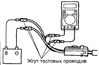
1. Disconnect the oxygen sensor connector and connect the test harness.
Engine 4G15.
Engine 4G93.
2. Measure the resistance between pins "1" (red test harness clamp for front sensor) And "3" (blue test harness clamp for front sensor) oxygen sensor connector.
Rated value (at 20°C) - 4.5 - 8.0 Ohm
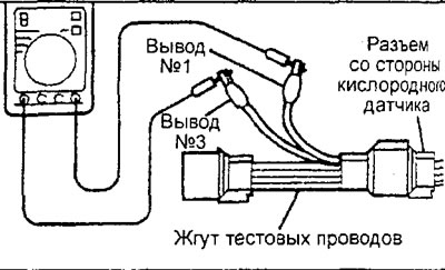
Front oxygen sensor.
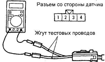
Rear oxygen sensor.
3. If the circuit is open, replace the oxygen sensor.
4. Warm up the engine (coolant temperature over 80°C).
5. Apply battery voltage to the oxygen sensor connector terminals by connecting to terminal "1" battery positive terminal wire, and to the terminal "3" - a wire of the negative plug of the rechargeable battery.
Warning: do not reverse the polarity, incorrect wiring may damage the oxygen sensor.
6. Connect a digital voltmeter to the terminal "2" (black test harness clip for front sensor) and to the conclusion "4" (white test harness clamp for front sensor).
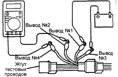
Front oxygen sensor.
Rear oxygen sensor.
7. While periodically depressing the accelerator pedal, measure the output voltage of the oxygen sensor. When the air/fuel mixture becomes slightly richer as the engine speed increases (overclocking), a working oxygen sensor should give a voltage of 0.6 -1.0 V.
8. If there are defects, replace the oxygen sensor.
9. Disconnect the test harness and connect the connector to the sensor.
Nozzles
1. Checking the sound of the nozzle operation.
A) Using a phonendoscope, check the operation of the injector (the presence of characteristic creaking sounds), when the engine is idling or when the engine is cranked by the starter.
b) Check that as the engine speed increases, the injector firing frequency also increases.
Attention: pay attention, even if the injector being tested does not work, sounds will be heard from the operation of the remaining injectors.
Note: If the sound of operation of the tested injector is not audible, then check the power supply circuit of the injector. If the circuits are normal, then check the injector or the electronic engine control unit for a malfunction.
Engine 4G93.
2. Checking the resistance of the winding of the solenoid valve of the nozzle.
A) Disconnect the connector of the injector to be tested.
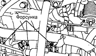
Engine 4G15.
b) Measure the resistance between the terminals of the injector connector.
Rated value (at 20°C) - 13-16 Ohm
V) Connect the injector connector.
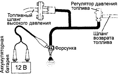
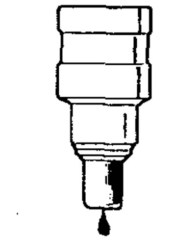
3. Checking the shape of the spray jet and the tightness of the nozzle.
A) Release residual pressure from the high pressure fuel line to prevent fuel splashing.
b) Remove the nozzle.
V) Install special tool (injector test kit), adapter, fuel pressure regulator, special clamps and injector.
G) Connect the tester to a standard diagnostic socket.
d) Turn the ignition key to position "ON" (ON) (do not start the engine).
e) Select sub-item No. 07 of item "ACTUATOR TEST" tester and activate the fuel pump.
and) Apply power to the injector and check the quality of fuel atomization. The condition of the injector is satisfactory if the fuel spray jet has a uniform structure without visible drops of fuel.
h) Disconnect power from injector and check for leaks (atomizer and locking needle) nozzles.
Nominal - 1 drop or less per minute
And) Apply power to the injector without turning on the fuel pump. Then, after the fuel stops coming out of the injector, disconnect the special tool and reset the injector.
To) Disconnect the tester.
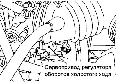
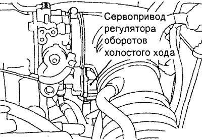
Idle speed control servo
Trigger sound check
1. Make sure that the temperature of the coolant is not higher than 20°C.
Note: It is also possible to disconnect the ECT sensor connector and connect another 20°C ECT sensor to the harness side connector.
2. Check if the sound of the stepper motor is heard after the ignition is turned on (do not start the engine).
Engine 4G15.
Engine 4G93.
3. If the sound of operation of the stepper motor is not audible, then check the circuits, the power supply of the idle speed control servo. If the circuit is normal, then the malfunction is in the servo or the electronic engine control unit.
Winding resistance test
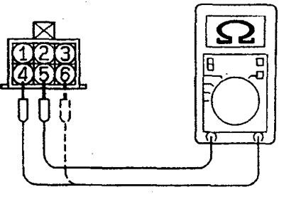
1. Disconnect the idle speed control servo connector.
2. Measure the resistance between the terminal "2" and conclusion "1" or "3" connector on the servo side.
Rated resistance (at 20°C) — 28 - 33 Ohm
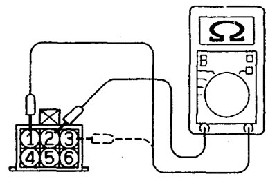
3. Measure the resistance between the terminal "5" and conclusion "6" And "4".
Rated resistance (at 20°C) — 28-33 Ohm
Checking the operation of the servo
1. Remove the throttle body.
2. Remove the idle speed control servo.
3. Connect the test lead harness to the servo.
4. Apply a voltage of approximately 6V to the white "5" and green "2" test harness leads.
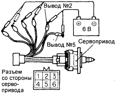
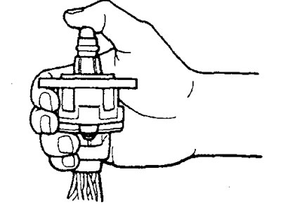
5. Mount the servo as shown in the figure and connect the negative wire from the 6V power supply to each of the listed terminals in the following order. At the same time, check if you can feel a slight vibration of the running stepper motor.
A) To red and black terminals (conclusions "1" And "4");
b) To blue and black pins (conclusions "3" And "4");
V) To blue and yellow terminals (conclusions "3" And "6");
G) To red and yellow terminals (conclusions "1" And "6");
d) To red and black terminals (conclusions "1" And "4");
e) Repeat the test in reverse order from point "d" to point "A".
6. If, as a result of these checks, a slight vibration of a working servo is felt, then it is considered serviceable.