Contents: General information ⤓ Standard troubleshooting scheme ⤓ Checking the "CHECK ENGINE" indicator ⤓ Reading diagnostic trouble codes…⤓ Clearing diagnostic trouble codes ⤓ Car diagnostics ⤓ Recommendations for troubleshooting…⤓ Checking using the "SERVICE DATA"…⤓ Current engine status data ("freeze…⤓ Troubleshooting during road tests ⤓ Explanations on the operation of the…⤓ Table. "Freeze frame" of data. ⤓ Table. Diagnostic trouble codes…⤓ Table. Diagnostic trouble codes…⤓ Table. Checking the system using the…⤓ Table. Checking the system using the…⤓ Table. Checking the system using the…⤓
General information
1. Type of self-diagnostic system.
a) The models use a self-diagnostic system of the EOBD or OBD-II type, the standard diagnostic code of which consists of one letter and 4 digits (for example: "P0000"). The numbering of such codes is continuous, i.e. the fault codes for different systems are not repeated.
b) On models with the OBD-II system, a new "freeze frame" data function has been added to the engine control unit (freeze frame data). When a fault is detected by the self-diagnosis system, the corresponding diagnostic code will be recorded and the current parameters of the main components and systems of the engine at that moment will be recorded ("freeze frame" of data). This data, read with the tester, can simplify the analysis of the conditions of the fault occurrence.
2. Features of diagnostics using a tester.
a) The algorithm of the Mitsubishi diagnostic system is slightly different from the standard algorithm (OBD2 protocol), therefore, to perform correct diagnostics, it is recommended to use the MUT-II tester.
b) It is recommended to connect the tester (MUT-II) with the ignition off, as a malfunction may occur in some types of electronic control units.
c) Before connecting the tester to the diagnostic connector, make sure that the condition and shape of the connector terminals are normal.
3. Diagnostic connector.
The vehicle was equipped with one standard 16-pin main diagnostic connector (located under the instrument panel).
4. Explanations on the operation of the "CHECK ENGINE" indicator:
- a) The indicator lights up for a few seconds immediately after the ignition is turned on to indicate that the indicator itself is functioning normally.
- b) Next (after starting or with the engine running), the indicator lights up to warn the driver that the self-diagnostic system has detected a malfunction.
Note: If the indicator lights up due to a malfunction of the electronic control unit, it is impossible to establish communication between the tester and the electronic control unit, and it is not possible to read diagnostic codes.
c) Intermittent flashing of the indicator indicates the presence of a temporary fault. It may continue as long as a major fault affects the emission control system or other systems (e.g., damage to the catalytic converter due to misfiring).
d) In the event of a critical fault (the presence of a serious defect in the fuel injection system or the exhaust gas toxicity reduction system), the indicator will light continuously while the vehicle is moving until the fault code is cleared after the fault has been corrected (i.e. after repair).
Note: Clearing the fault code does not correct the fault.
d) The indicator will go out when the ignition is turned off (key: "OFF").
5. Conditions under which the illuminated "CHECK ENGINE" indicator may go out due to a signal from the electronic control unit when the ignition is on (the fault code remains).
Note: For any fault, a cycle means starting and stopping the engine or three trips (road tests of the vehicle) during which the fault is monitored
a) For a transmission fault: If the engine control unit has not detected a fault within three cycles under the appropriate modes and conditions (see conditions for setting the code).
b) For a malfunction in the exhaust emission system (misfiring): if the electronic engine control unit has not detected a malfunction during the cycle under similar engine operating conditions (crankshaft speed, coolant temperature, etc.) under which the malfunction was first detected.
6. Explanations on the operation of the self-diagnostic system.
a) The electronic engine control unit monitors input and output signals (some constantly, others - only under certain conditions). If a constant or specified period of time malfunction of the system is detected, or if after the first incorrect signal several more similar signals are received by the electronic engine control unit, the engine control unit will perceive this as a malfunction, write the corresponding malfunction code into memory and send a signal to the output of the self-diagnostic system.
Note:
- Typically, if the ECU detects a fault, the "CHECK ENGINE" indicator will illuminate and a fault code will not be stored until the engine is restarted and the same fault is detected again.
- − If a malfunction of the ignition coil (power transistor) occurs, the "CHECK ENGINE" indicator will light and the fault code P0300 will be recorded at the first detection (this fault is critical); since damage to the catalytic converter occurs).
b) Since the memory device (RAM of the ECU) is powered directly by the battery, the diagnostic results are saved even when the ignition switch is turned to the "OFF" position. The trouble codes will be erased when the battery terminal or the ECU connector is disconnected. In addition, the trouble codes are erased if a signal to erase the trouble codes is sent from the tester to the ECU with the ignition switch turned on (the key is in the "ON" position).
Note: If you disconnect the connector of any sensor with the ignition on (key in the "ON" position), the electronic control unit will perceive this as a malfunction and the corresponding code will be written into the control unit's memory. In this case, delete the malfunction codes.
Standard troubleshooting scheme
1. Simulate signs of a malfunction to check for their presence and determine the nature and conditions of occurrence (engine operating mode, operating conditions, etc.).
2. Read the fault codes and determine the causes of the fault, the components to be checked and the order in which they are checked.
3. Check the input signals of the electronic engine control unit using a tester or motor tester. If the signals are normal, then the corresponding sensor (element) is in good condition. Proceed to check the next component.
4. Check the output signals of the ECU using a motor tester and check the operation of the actuators using the ACTUATOR TEST menu item of the tester. If the signals of the ECU and the actuator are normal, then the actuator control is normal. Proceed to checking the next component.
5. If the ECU signals are normal, check and, if necessary, repair the wiring of the system components. After repair, check the ECU signals again. If the signals are normal this time, check the input and output signals for the next component to be checked.
6. If the wiring is OK, but the input and output signals of the ECU are not normal, check the individual components of the system and, if necessary, repair or replace them. After repair, check the signals of the ECU again. If the signals are normal this time, check the signals for the next component to be checked.
7. Recheck for signs of malfunction and repair.
If the suspected wiring circuit and specific components are checked and no faults are found, but the ECU input and output signals are abnormal, then evaluate the symptoms more closely (the initial diagnosis may have been incorrect or incomplete). With further testing, try to expand the fault search to other groups of components (repair if necessary).
8. Try to simulate the symptoms of the malfunction to be sure that the malfunction has been eliminated. Eliminate the cause of the malfunction to prevent the defect from reoccurring.
Checking the "CHECK ENGINE" indicator
1. Turn the ignition switch to the "ON" position and make sure that the "CHECK ENGINE" indicator comes on for approximately 5 seconds and then goes out.
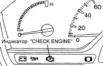
2. If the indicator does not light, check the wiring, fuse and indicator lamp.
Reading diagnostic trouble codes using a tester
1. Prepare the vehicle for inspection as follows.
a) Make sure that the battery is in good condition, as fault detection is impossible if the battery voltage is low.
b) Turn off all additional equipment.
c) Set the CVT or automatic transmission selector lever to the "N" position.
Caution: Do not disconnect the battery until the diagnostic results have been fully read, as the fault code will be cleared from the ECU memory when the battery or ECU connector is disconnected.
Note: If the diagnostic trouble codes have been cleared, the Freeze Frame Data fault information will also be cleared from the memory. Therefore, if necessary, read the Freeze Frame Data fault before clearing the trouble codes from the ECU memory.
2. Turn the ignition switch to the "OFF" position.
3. Connect the tester to the diagnostic connector under the instrument panel.
Caution: To prevent damage to the tester, the ignition must be switched off (ignition key in the "OFF" position) when connecting or disconnecting.
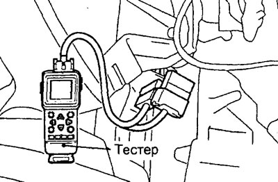
4. Turn on the ignition and read the diagnostic codes.
Note: The fault codes are listed in the Diagnostic Trouble Codes table.
5. After completing the test, turn the ignition switch to the "OFF" position and then disconnect the tester from the diagnostic connector.
Clearing diagnostic trouble codes
Note: After repairs are completed, clear the fault codes from the ECU memory.
1. Turn the ignition key to the "OFF" position.
2. If a tester is used, connect it to the diagnostic connector and erase the codes,
3. When the tester is not in use, disconnect the cable from the negative terminal of the battery for 10 seconds or more.
Caution: After disconnecting the wire from the negative terminal of the battery, the contents of the memory of the electronic control units of other systems will be lost.
4. Turn the ignition key to the "ON" position, then check that the normal status code is displayed.
5. After warming up the engine, let it idle for at least 10 minutes.
Car diagnostics
1. Prepare the vehicle for testing (see "Reading diagnostic trouble codes using a tester").
2. Connect the tester to the diagnostic connector under the instrument panel.
Caution: Before connecting the tester, turn off the ignition.
3. Turn on the ignition and read the diagnostic codes.
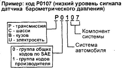
4. Description of the structure of the standard diagnostic trouble code for the 0E3D-II type system.
a) The letter indicates the purpose (area of application) of the faulty device: P - transmission (engine and gearbox), C - chassis, B - body, U - on-board electrical system, b) The first digit of the code after the letter indicates either a group of general codes according to SAE (0) or a group of specialized codes of the manufacturer (1).
c) The second digit of the code after the letter indicates the specific vehicle system in which the fault is present. For example, if the application area is the transmission (P), then the following 8 systems are defined for it: 1 - fuel and air supply system, 2 - fuel and air supply system (only types of faults in the injector circuit), 3 - ignition system or misfiring in cylinders, 4 - additional control system for reducing toxicity of exhaust gases (emissions), 5 - vehicle speed control system and idle speed control system, 6 - circuits of various electronic control systems, 7 and 8 - transmission (gearbox).
d) The remaining 2 digits indicate a specific component of the system.
Recommendations for troubleshooting by codes
1. Before searching for the cause of the malfunction, check that the battery voltage is 10 V or more, then check the ground circuit of the engine control unit.
2. If the DTC continues to appear even though the test showed that the systems/circuits being tested are normal (no faults were found), then replace the ECM with a known good one, road test and retest.
3. Replace the electronic engine control unit only after checking the voltage at its terminals to confirm that there is no open or short circuit in the circuits.
4. If the diagnostic code is not set and the engine stalls or does not start, then if the diagnostic circuit is normal, replace the ECM.
5. For most items diagnosed with codes, the main causes of failure are:
- a) Defect of the corresponding element (indicated in the code detail, see code table);
- b) Poor contact in the element connector, broken wiring or short circuit in the element circuit (power supply circuit, ground, signal);
- c) Defective electronic engine control unit.
Checking using the "SERVICE DATA" and "ACTUATOR TEST" functions of the tester
1. Perform a check using the menu item "SERVICE DATA" and "ACTUATOR TEST" of the tester. If a fault is detected, check the vehicle's electrical wiring, relevant units and components.
Caution: When moving the selector lever to the "D" position, it is necessary to keep the brake pedal depressed to prevent the vehicle from moving.
Note: the open state time of the injector is determined when the crankshaft is rotated by the starter at a frequency of no more than 250 rpm, when the supply voltage is at least 11 V.
2. After repair, re-test with a tester and make sure that the repair has made the abnormal input and output signal normal.
3. Clear diagnostic trouble codes from the engine control unit memory.
4. Start the engine and road test it to ensure that the problem has been corrected.
Current engine status data ("freeze frame")
If multiple faults are detected, the ECU memory will store a freeze frame of data only for the fault detected first. The freeze frame data table lists the components whose status information will be written to the ECU memory if a fault is detected.
Troubleshooting during road tests
1. Ready for road testing.
a) The electronic engine control unit constantly determines the state of the following parameters to determine whether they comply with the norm, while storing the received data in memory:
- (Engine 4G15) oxygen sensor (code P0130), oxygen sensor heating element (code P0135).
- (Engine 4G15) oxygen sensors (codes P0130 and P0136), oxygen sensor heating elements (codes P0135 and P0141).
b) This data can be read using a tester (if the parameter status was determined earlier, this is confirmed by the corresponding entry, for example "Complete").
Note: If fault codes have been cleared or the battery cables have been disconnected, this data will also be erased from the memory.
2. Troubleshooting with a tester during road tests.
a) Using the tester, switch the diagnostic mode of the engine control unit to the "DIAGNOSIS 2" mode.
b) Perform road tests.
c) Read the fault codes and determine the location of the fault.
d) Turn the ignition off and then on.
Note: After turning off the ignition, the engine control unit will automatically switch to the diagnostic mode "DIAGNOSIS 1".
d) Clear the fault codes.
Explanations on the operation of the system in emergency mode (replacing incorrect signals)
When the self-diagnostic system detects a malfunction of one of the main sensors, the engine management system switches to emergency control mode (FAIL SAFE FUNCTION), replacing the incorrect signal with a signal previously recorded in the memory of the electronic control unit, so that the car can continue moving (to the place of repair).
(Article reprinted from the website MitsubishiMan)
1. If the absolute pressure sensor in the intake manifold (engine 4G 15) or the mass air flow sensor (engine 4G93) is faulty, then:
- a) The signals from the throttle position sensor and the crankshaft position sensor are used to determine the basic injector opening period (fuel delivery) and the basic ignition timing angle in accordance with the specified program.
- b) The idle speed control servo is fixed in the programmed position, as a result of which the idle speed is not regulated.
Table. "Freeze frame" of data.
| № | Parameter | Unit of measurement. |
| 21 | Coolant temperature sensor | °C |
| 22 | Crankshaft position sensor | rpm |
| 24 | Vehicle speed sensor | km/h |
| 81 | Long-term fuel balance | % |
| 82 | Short-term fuel balance | % |
| 87 | Calculated load | % |
2. (Engine 4G15) If the intake manifold air temperature sensor is faulty, the intake manifold air temperature is taken to be 45°C.
3. (Engine 4G93) If the intake air temperature sensor is faulty, the intake air temperature is taken to be 25°C.
4. If the throttle position sensor is faulty, there is no increase in fuel supply when the accelerator pedal is pressed (based on the signal from the throttle position sensor).
5. If the coolant temperature sensor is faulty, then:
The engine coolant temperature is taken to be 80°C (the system will continue to operate in steady state (even if the sensor signal becomes normal) until the ignition key is turned to the "LOCK" position).
6. If the camshaft position sensor is faulty, then:
Fuel is supplied to all cylinders simultaneously (it is assumed that at the moment the ignition is turned on, the piston of the first cylinder was not at TDC).
7. If the barometric pressure sensor is faulty, the air pressure is taken as 101 kPa (758 mm Hg)
8. If the knock sensor is faulty, the electronic control unit switches the ignition timing from the value set for PREMIUM or SUPER gasoline (95 RON according to the research method) to the value set for REGULAR or STANDARD gasoline (91 RON according to the research method).
9. If the ignition coil (power transistor) is faulty, then the fuel supply to the cylinders for which the ignition signal is incorrect is stopped.
10. (Engine 4G 15) If the oxygen sensor is faulty, the air-fuel ratio is not regulated (no feedback control).
11. If there is no signal from the FR output of the generator, then the generator output voltage is not controlled by the electrical load (it works like a normal generator).
Table. Diagnostic trouble codes (engine 4G15).
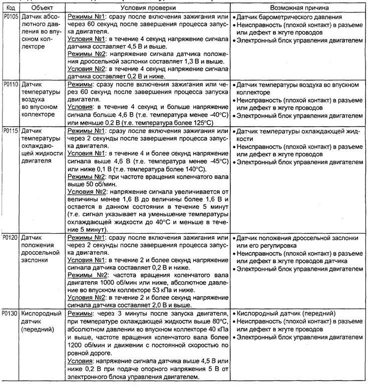
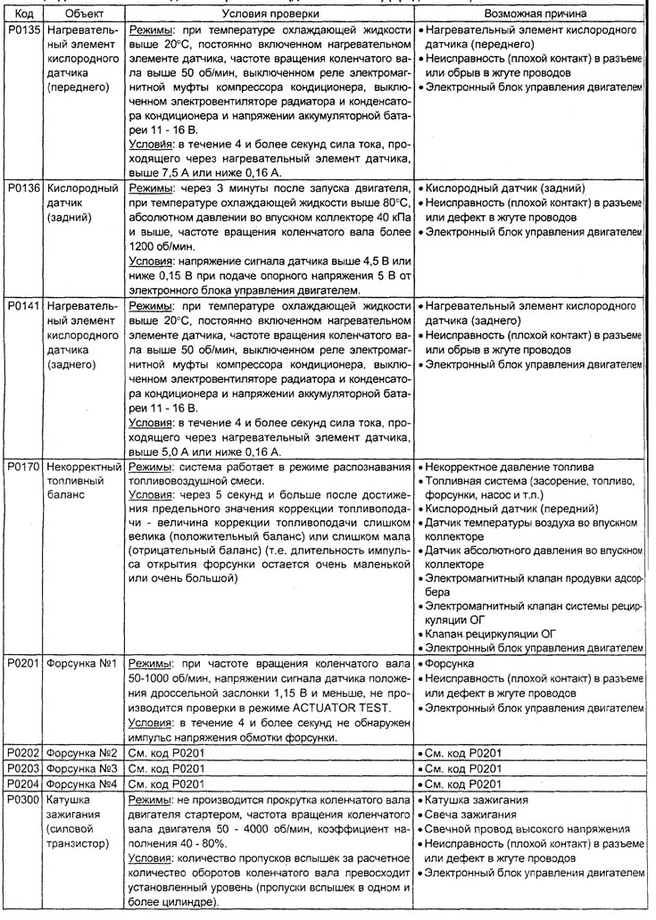
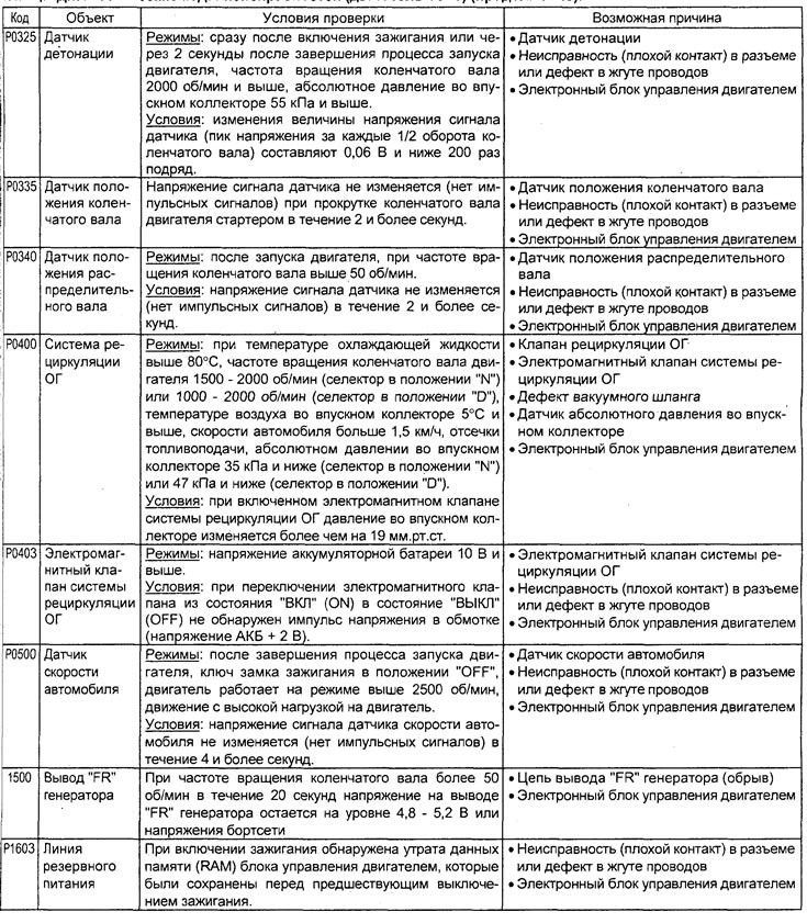
Table. Diagnostic trouble codes (engine 4G93).
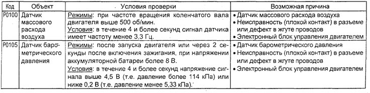
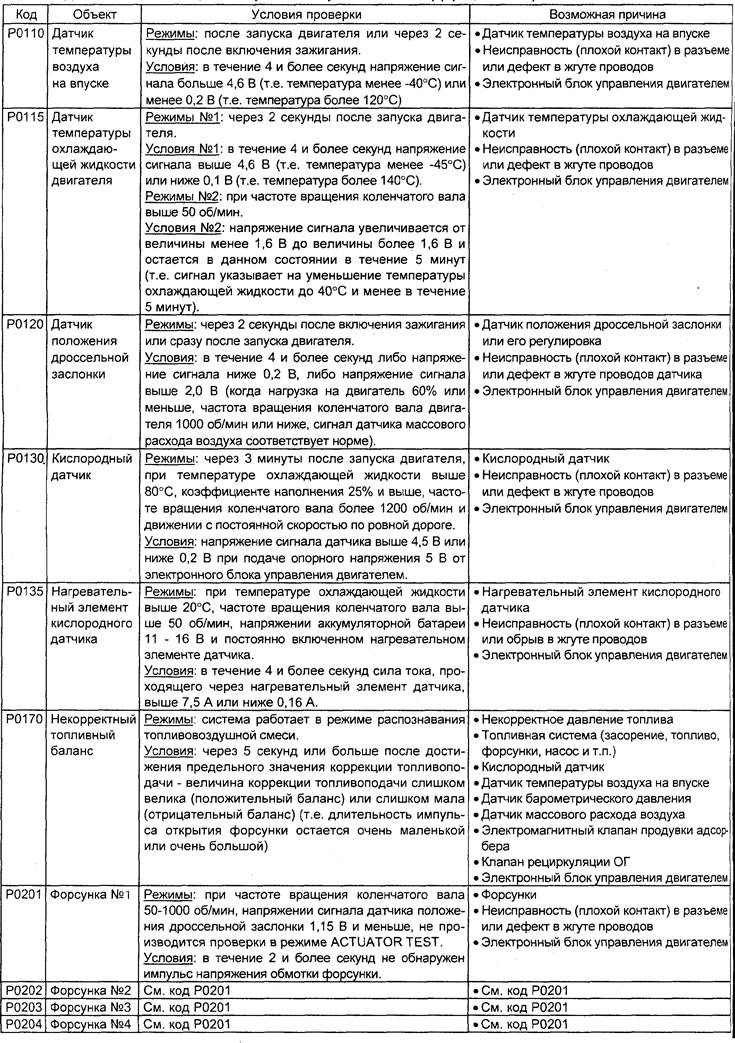
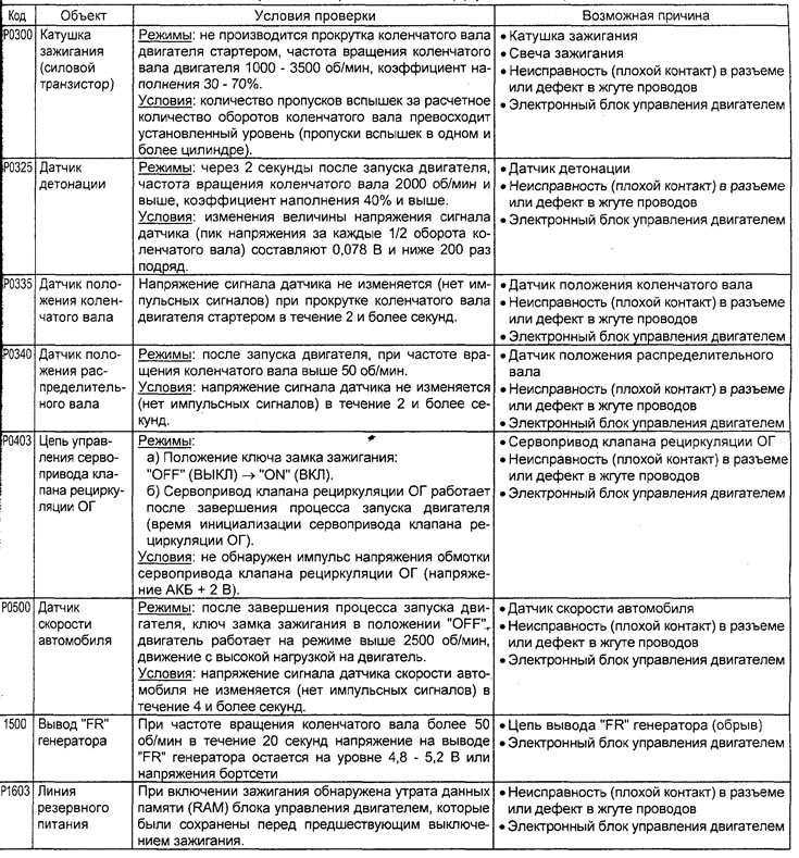
Table. Checking the system using the "SERVICE DATA" function of the tester (engine 4G15).
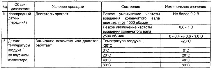
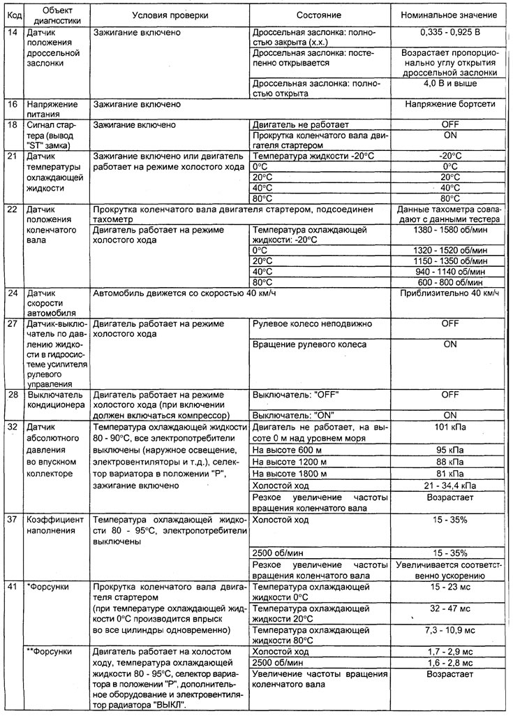
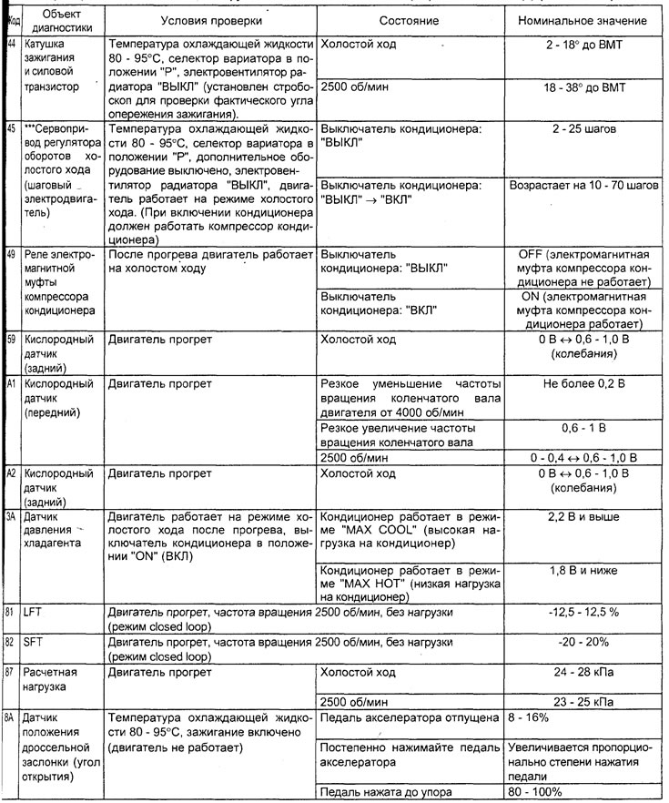
Note: in the table the following symbols are used:
- - When moving the CVT or automatic transmission selector lever to the "D" position, it is necessary to keep the brake pedal fully depressed to prevent the vehicle from moving forward;
- The injector response time is determined by the voltage supply time and the engine crankshaft speed (250 rpm or less). As the crankshaft speed increases, the injector response time decreases.
- On a new car (with a mileage of 500 km or less), the result can sometimes differ by 10% upwards from the nominal value.
- On a new car (with a mileage of 500 km or less), the result can sometimes differ by 30 steps upwards from the nominal value.
- − LFT - long-term fuel balance.
- SFT - short-term fuel balance.
Table. Checking the system using the "SERVICE DATA" function of the tester (engine 4G93).
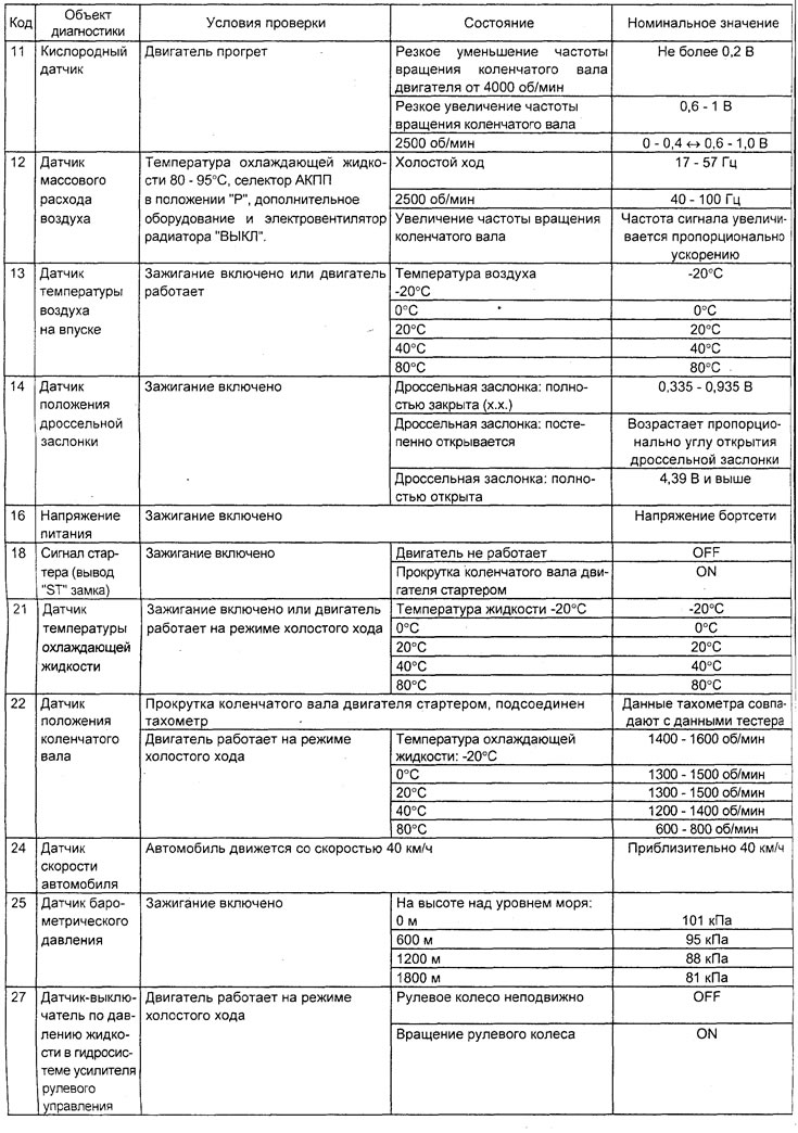
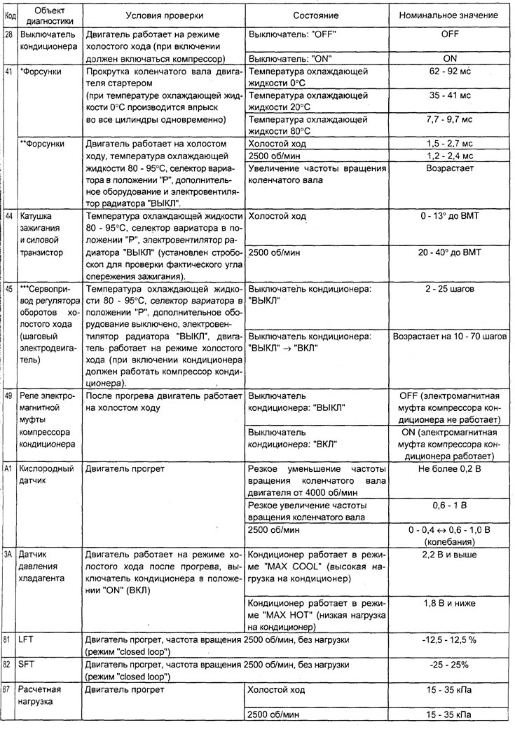

Note: in the table the following symbols are used:
- When moving the CVT or automatic transmission selector lever to the "D" position, it is necessary to keep the brake pedal fully depressed to prevent the vehicle from moving forward;
- The injector response time is determined by the voltage supply time and the engine crankshaft speed (250 rpm or less). As the crankshaft speed increases, the injector response time decreases.
- On a new car (with a mileage of 500 km or less), the result can sometimes differ by 10% upwards from the nominal value.
- On a new car (with a mileage of 500 km or less), the result can sometimes differ by 30 steps upwards from the nominal value.
- LFT - long-term fuel balance.
- SFT - short-term fuel balance.
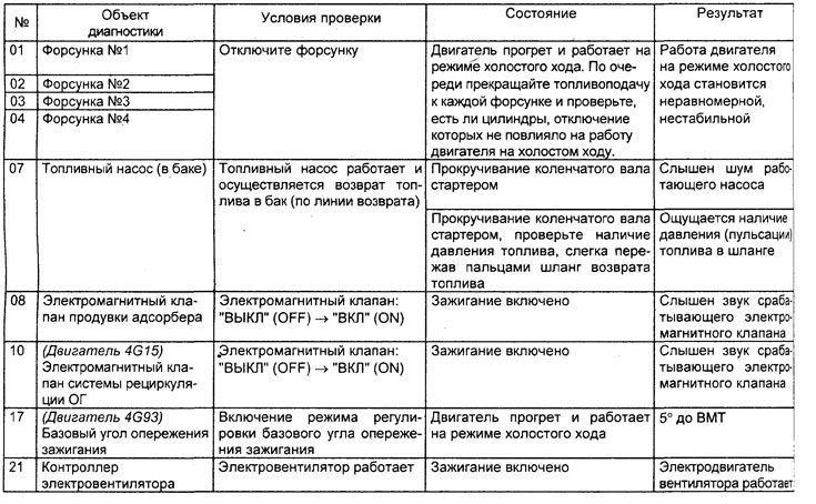
Table. Checking the system using the "ACTUATOR TEST" function of the tester.