Contents: Mass Air Flow Sensor (4G93 Engine) ⤓ Camshaft position sensor and…⤓ Nozzles ⤓ Idle speed control servo ⤓ Ignition coil and power transistor ⤓ Checks on the engine control unit…⤓ Checking the voltage at the…⤓ Checking the resistance at the…⤓ Table. Checking the voltage at the…⤓ Table. Checking the resistance…⤓ Table. Checking the voltage at the…⤓ Table. Checking the resistance…⤓
Note:
- To connect the oscilloscope sensor (motor tester) to the sensor being tested, connect the test wire harness between the connectors (all terminals must be connected). Perform the test on the terminals of the test wire harness.
- For testing, it is permissible to connect the oscilloscope sensor (motor tester) to the corresponding terminal of the engine control unit connector, instead of connecting to the terminal of the connector of the sensor being tested.
Mass Air Flow Sensor (4G93 Engine)
1. Connect the oscilloscope (motor tester) sensor to terminal "3" of the mass air flow sensor connector.
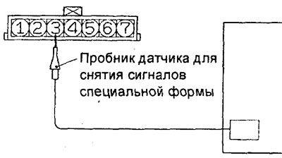
2. Compare the sensor signal waveform on the oscilloscope with the figure when the engine is running at idle speed.
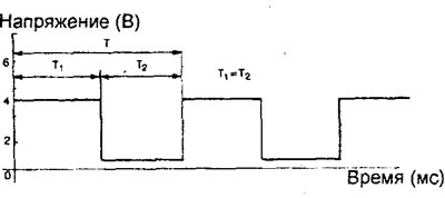
Division value: X - 5 ms/d, Y - 2 V/d
3. Check that the period "T" is reduced and the signal frequency increases with increasing engine crankshaft speed.
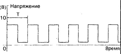
4. Possible deviations from the normal signal shape.
a) Due to a fault in the circuits between the mass air flow sensor and the engine control unit, the signal appears in the form of rectangular pulses even if the engine is not running.
b) Due to damage to the mass air flow sensor (damage to the straightener or vortex former column), the signal is present as an unstable variable frequency curve. However, if high voltage leaks (from the ignition system) occur when the engine crankshaft speed increases, temporary distortions will appear on the curve, even with a serviceable mass air flow sensor.
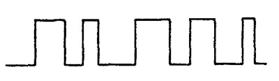
Camshaft position sensor and crankshaft position sensor
1. To check the camshaft position sensor signal waveform, connect the engine tester sensor to terminal "2" of the sensor connector.
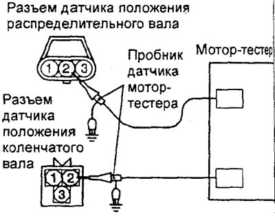
Engine 4G15.
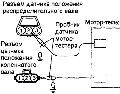
Engine 4G93.
2. To check the signal waveform of the crankshaft position sensor, connect the motor tester sensor to terminal "3" of the sensor connector.
3. Compare the shape of the sensor signal on the oscilloscope with the figure when the engine is idling. Check that the period "T" is reduced as the engine crankshaft speed increases.
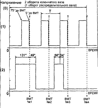
Normal waveform of camshaft position sensor and crankshaft position sensor. (1) - crankshaft position sensor, (2) - camshaft position sensor. Division value: X - 10 ms/d, Y - 2 V/d.
(The original can be found on the website: «MitsubishiMan.ru»)
4. Possible deviations from the normal signal shape.
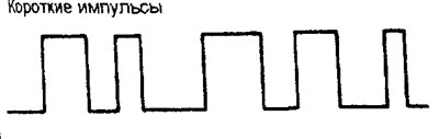
a) Due to a fault in the circuits between the sensor and the engine control unit, the signal appears in the form of short pulses, even if the engine is not running.
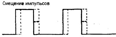
b) Due to weakening of the timing belt tension or a faulty sensor rotor, the rectangular pulses shift to the right or left.
Nozzles
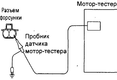
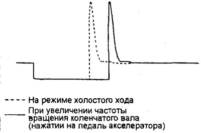
1. Connect the motor tester sensor to terminal "2" of the connector of the injector being tested. Repeat the procedure for each injector.
2. Check that the shape and duration of the injector control signal match the figure when the engine is running at idle speed.
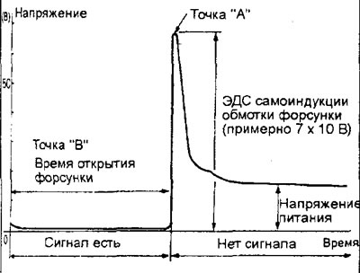
Injector control signal shape and duration. Division value: X - 0.5 ms/d, Y -1 V/d.
3. When observing the signal, pay attention to the following points.
a) Point "A": Amplitude (signal height) of the self-induction EMF of the injector electromagnetic valve winding.
Note: Due to the short circuit in the injector solenoid valve winding, the magnitude of the self-induction EMF of the winding is small or does not occur at all.
b) Point "B": Duration of the injector control signal (injector opening time).
Note: When the accelerator pedal is pressed sharply, the duration of the injector control signal will initially increase significantly, but will then correspond to the engine crankshaft speed (returns to its normal form).
Idle speed control servo
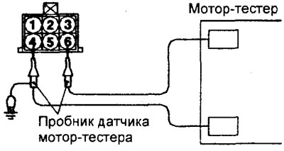
1. Connect the oscilloscope sensor (motor tester) to terminals "1", "3", "4" and "6" of the connector on the side of the idle speed control servo solenoid valve.
2. In the specified engine operating modes, check that a normal waveform signal appears during stepper motor operation (see figure).
a) When the ignition switch is turned from the "OFF" position to the "ON" position, but the engine is not started (coolant temperature is 20°C or lower).
b) With the engine idling, turn on the air conditioner (turn the switch to the "ON" position).
c) Immediately after starting a warm engine (approximately 1 minute).
3. When observing the signal, pay attention to the following points.
a) Point "A" - the presence or absence of EMF induced during rotation of the electric motor.
Note: if the electric motor is faulty, then the back-EMF does not occur when the electric motor rotates, or its value is very small.
b) Point "B" is the value of the self-induction EMF (inductive surge, 3x10 V).
Note: if a short circuit occurs in the winding, the self-induction EMF arising in the winding does not appear or its value is very small.
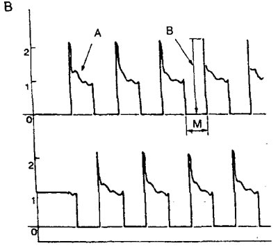
Division value: X-20 ms/div., Y - 1 V/div. Region "A" - back-EMF arising during rotation of the electric motor. Region "B" - self-induction EMF in the winding.
4. An example of deviation from the normal signal shape.
a) Due to a malfunction of the stepper motor (it does not work), the back-EMF does not appear when the motor rotates.
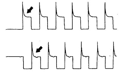
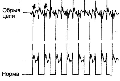
b) Open circuit between the stepper motor and the electronic engine control unit. When the circuit is open, current does not flow in the motor winding (the voltage does not drop to 0 V). Note that the back-EMF signal that occurs when the motor rotates (with a functioning stepper motor) is only slightly different from the signal when the winding circuit is open.
EGR valve servo (engine 4G93)
1. Disconnect the valve servo connector and install the test lead harness between the connectors (all leads must be connected).
2. Connect the oscilloscope (motor tester) sensor to the specified terminals of the connector on the EGR valve servo side in the following order: "1", "3", "4" and "6".
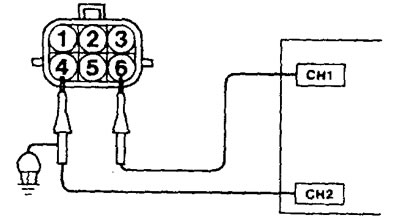
3. In the specified engine operating modes, check that a normal waveform signal appears during stepper motor operation (see figure).
When the ignition switch is turned from the "OFF" position to the "ON" position but the engine is not started.
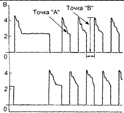
EGR valve servo signal form. Division value: X - 25 ms/div, Y - 1 V/div. Point "A" - back-EMF arising from the rotation of the electric motor. Point "B" - self-induction EMF in the winding.
4. When observing the signal, pay attention to the following points.
a) Point "A" - the presence or absence of EMF induced during rotation of the electric motor.
Note: if the electric motor is faulty, then the back-EMF does not occur when the electric motor rotates, or its value is very small.
b) Point "B" is the value of the self-induction EMF (inductive surge, 2x10 V).
Note: if a short circuit occurs in the winding, the self-induction EMF arising in the winding does not appear or its value is very small.
5. Example of deviation from the normal signal shape.
a) Due to a malfunction of the stepper motor (it does not work), the back-EMF does not appear when the motor rotates.
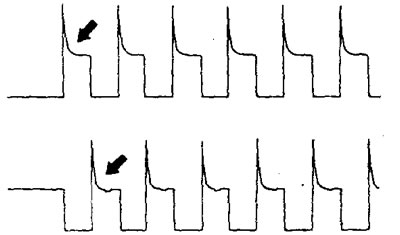
b) Open circuit between the stepper motor and the electronic control unit of the engine and automatic transmission. When the circuit is open, the current does not flow in the winding of the electric motor (the voltage does not drop to 0 V). Note that the back-EMF signal that occurs when the electric motor rotates (with a serviceable stepper motor) differs only slightly from the signal when the winding circuit is open.
Ignition coil and power transistor
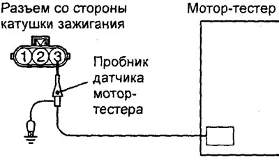
1. Connect the motor tester sensor to terminal "3" of the connector of the ignition coil being tested.
2. Check that the signal shape matches the figure when the engine is running at 1200 rpm.
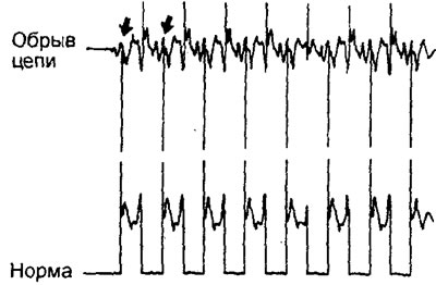
Note: When observing the signal, pay attention to the state of the voltage increase section and the maximum voltage.
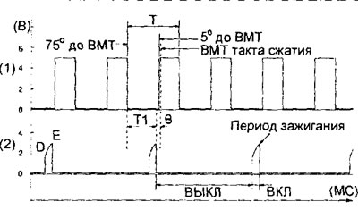
(1) - crankshaft position sensor signal, (2) - power transistor signal. Division value: X - 10 ms/d. Y - 2 V/d.; "T" - time of crankshaft rotation by 180°; "T1" - data processing time by the engine control unit; "b" - ignition timing angle.
3. In the normal state, the signal has a section of voltage growth in the upper right part (voltage growth from approximately "D" to "E").
Nominal value:
- "D" is approximately 2.0 V
- "E" approximately - 4.5 V
4. Examples of deviations from the normal signal shape (signal shape: when the engine crankshaft is cranked by the starter).
a) Due to a break in the circuit in the primary winding of the ignition coil, the signal is rectangular (the upper right section of voltage growth is missing), and the maximum voltage reaches only the above-mentioned value "D".
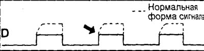
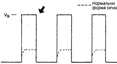
b) Due to a malfunction of the power transistor, when the power transistor is turned on (position "ON"), supply voltage (Ve - on-board network voltage) occurs.
Checks on the engine control unit connector
Note:
- If any deviation from the nominal value is detected, check the corresponding sensor, actuator and corresponding wires.
- After repairing or replacing a component, retest to ensure that the problem has been corrected.
Checking the voltage at the connector terminal on the side of the electronic control unit
1. Disconnect the ECU connector and connect the test lead harness between the connectors or use the voltmeter needle probes to test the connector on the harness side.
Caution: A short circuit of the positive probe connected to the connector terminal to ground may cause damage to the wiring, sensor, electronic control unit, or all of the above.
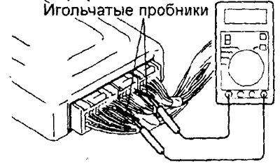
2. With the ECU connector connected, measure the voltage between the ground terminals of the ECU and each corresponding terminal of the ECU connector.
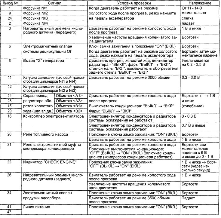
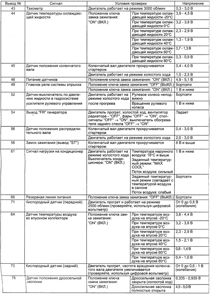
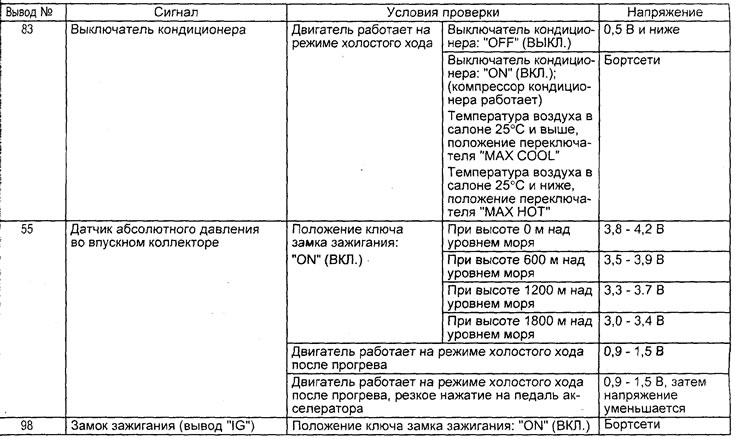
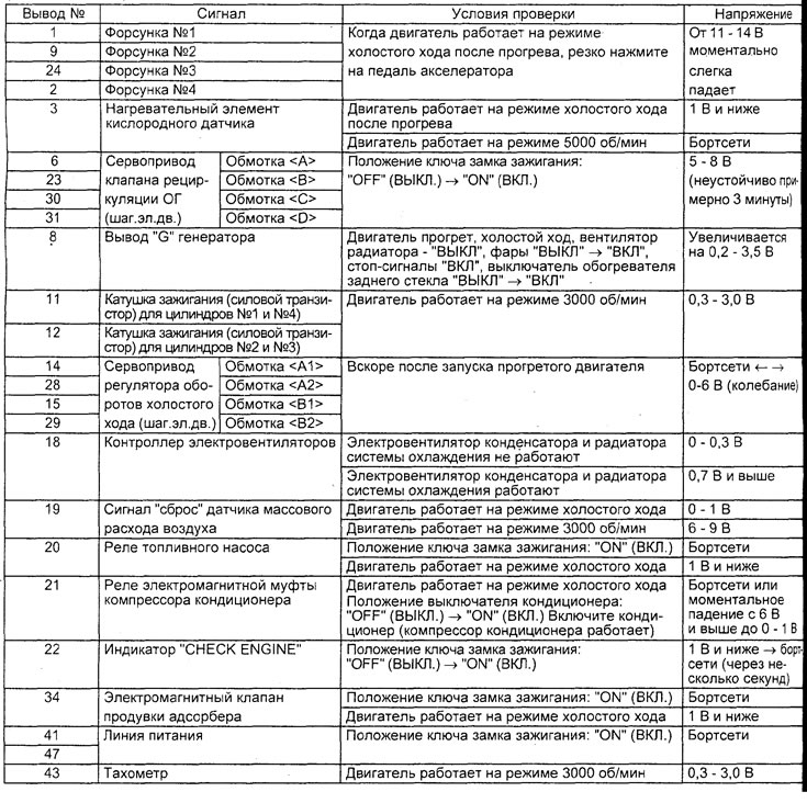
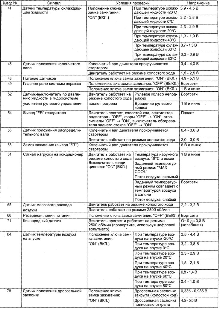
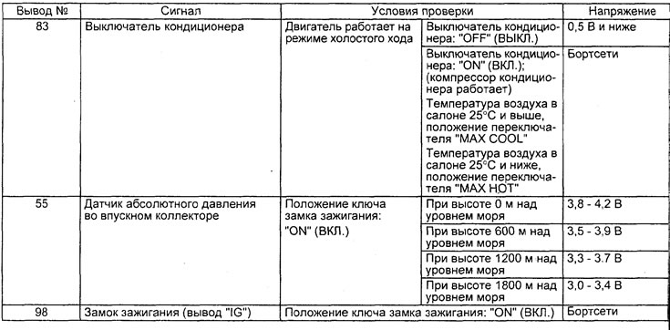
3. The terminals and values to be checked are indicated in the table "Checking the voltage at the terminals of the engine control unit connector".
4. The location of the terminals is shown in the corresponding figures.
Checking the resistance at the terminals of the electronic unit connector on the wiring harness side
1. Before starting the check, turn the ignition key to the "OFF" position and disconnect the ECU connector.
2. Connect the test lead harness to the connector on the harness side, then check the resistance and continuity between the connector terminals.
Attention:
- Do not use needle ohmmeter probes.
- If the terminals being tested are mixed up, or the terminals are incorrectly connected to ground, this may result in damage to the wiring, sensors, electronic control unit and/or ohmmeter.
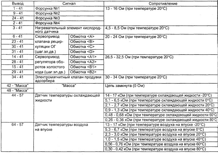
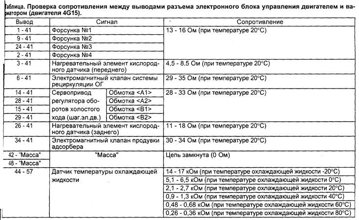
3. The terminals and values to be checked are indicated in the table "Checking the resistance at the terminals of the electronic control unit connector on the wiring harness side".
4. The location of the terminals is shown in the corresponding figure.

Connector from the side of the electronic control unit of the engine and variator (engine 4G15).
Table. Checking the voltage at the terminals of the connector of the electronic control unit of the engine and variator (engine 4G15).

Connector on the side of the wiring harness of the electronic control unit of the engine and variator (engine 4G15)
Table. Checking the resistance between the terminals of the electronic engine control unit connector and the variator (4G15 engine).


Connector from the side of the electronic control unit of the engine and automatic transmission (engine 4G93).
Table. Checking the voltage at the terminals of the connector of the electronic engine control unit and automatic transmission (engine 4G93).

Connector on the side of the wiring harness of the electronic control unit of the engine and variator (engine 4G93)
Table. Checking the resistance between the terminals of the connector of the electronic engine control unit and the variator (engine 4G93).