
English Русский
Български
Беларускі
Український
Српски
Hrvatski
Română
Polski
Slovenský
Magyar
Articles Bookmark Contacts Sitemap   
Company Audi Company Ford Company Hyundai Company Kia Company Mazda Company Mercedes-Benz Company Nissan
MitsubishiMan.ru


Home Colt Lancer Galant L200 Outlander Pajero Others
Carisma (1995-2004) Space Star (1998-2005)

Checking and adjusting the fuel injection timing (Mitsubishi Carisma)

  • Home
  • Mitsubishi
  • Carisma (1995-2004)
  • Power unit
  • Diesel engines FBQT
  • Checking and adjusting the fuel injection timing
0
Contents: Examination ⤓ Adjustment ⤓

Examination


1. Turn the crankshaft using the pulley mounting bolt to set the piston of the 1st cylinder to the TDC position in the compression stroke.

2. Turn the crankshaft in its normal direction of rotation another 13/4 turns.

3. Unscrew plug A on the high-pressure fuel pump (Fig. 4.6)
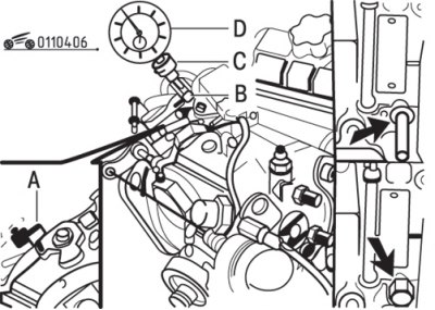


Fig. 4.6. Installation of the special tool (MB996030) for checking the injection timing and the location of the locking pin (arrow): A - cork; B – measuring rod; C – holder; D – hour indicator


4. Install the special tool:
  • install the guide bushing into the high pressure fuel pump;
  • insert the measuring rod B, which is part of the special tool, into the pump guide;
  • install and secure the C holder;
  • install the dial indicator head D and make sure that the pump plunger is recessed by at least 0.2 mm. Fasten the dial indicator head and set the indicator to 0.

Attention! The measuring rod and guide bushing are supplied and used as a set. It is not allowed to replace one of the parts with similar ones from another set.


5. Turn the crankshaft in its normal direction of rotation until the indicator shows 5.00 mm.


6. Apply slight force to the lock pin and at the same time continue to rotate the crankshaft until the lock pin enters the crankshaft hole.

7. Record the indicator reading.

8. This value should be 0.02 mm (indicated on the pump control lever).

9. If the measured value does not match the specified value, the fuel pump must be adjusted.
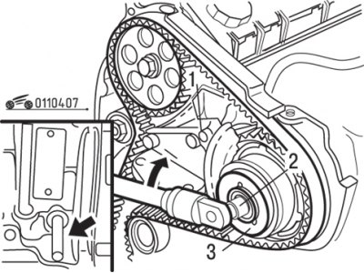


Fig. 4.7. Installing a special tool between the pump bracket and the pulley: 1 – special tool МВ996043; 2 – special tool МВ996036; 3 – pulley


10. Install the special tool (pulley lock) between the pump bracket and the pulley. Secure the tool with the bolt supplied with it (Fig. 4.7).

11. Install a hex socket onto the threaded sleeve and nut assembly. Loosen (clockwise) the threaded sleeve and nut assembly 1/8 of a turn. This will allow the pulley flange to move.

12. Remove the pulley retainer, lock pin and indicator head.

Attention! The plunger is not spring-loaded! When turning the crankshaft, the indicator head can be broken.


13. Turn the crankshaft another 1 3/4 turns, install the indicator head and make sure that the plunger is recessed by 0.2 mm. Check and adjust the fuel injection timing.


Adjustment
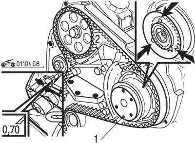


Fig. 4.8. Installing a special tool in three holes of the flange (arrows): 1 – special tool MB99G037


1. Install the special tool into the three holes of the flange (Fig. 4.8).

2. Rotate the tool together with the flange until the tool jaws grip the three internal grooves of the pulley.

3. Turn the tool together with the flange clockwise until the gaps in the pump are eliminated, then turn it further so that the amount of movement is 0.5 mm less than recommended.

4. Now turn the tool together with the flange counterclockwise until the adjustment value indicated on the pump is reached with an accuracy of ±0.02 mm.

5. Install the pulley retainer and secure it with the bolt provided with the tool.

6. Turn the bracket with bolt 2 so that the bracket has no play.

Attention! The pump pulley must not move (the arrow on the indicator head must not move).


7. Install the special tool (hexagonal socket head) onto the threaded sleeve and nut assembly and tighten the assembly (counterclockwise) to the rated torque.

8. Remove the special tool (pulley lock), lock pin and indicator head.

9. Turn the crankshaft further by 1 3/4 turns, secure the indicator head and check that the plunger has moved by 0.2 mm.


10. Check the fuel injection timing.

11. Remove the special tool together with the indicator head and measuring pin. Install the plug with a new O-ring.

12. Tighten the plug to a torque of 10 Nm.

13. Remove the locking pin and install the plug with a new sealing gasket.

14. Tighten the plug to 20 Nm.
This article is available at: russian, bulgarian, belarusian, ukrainian, serbian, croatian, romanian, polish, slovak, hungarian
This article was reviewed by: Dmitry Vasiliev
Share with friends:
◀ Previous
Carisma: Diesel engines FBQT
Next ▶

Checking and adjusting valve clearances
Checking and adjusting the accessory drive belt (cars with air conditioning)
Lubricants
Specifications and data
Checking and adjusting the engine idle speed
Checking and adjusting the increased engine crankshaft speed at idle during warm-up
Compression check
Adjusting the timing belt tension of the gas distribution mechanism
Crankshaft pulley — removal and installation
Similar materials for other Mitsubishi models

➤ Start of fuel supply by injection pump — checking and… Mitsubishi Colt 4 and 5 (1991-2003)
➤ Checking/adjusting the start of fuel supply by the… Mitsubishi Lancer 3 and 5 (1984-1992)
➤ Checking/adjusting the ignition timing Mitsubishi Galant 6 and 7 (1987-1998)
➤ Checking and adjusting the tension of auxiliary drive belts Mitsubishi L200 4 (2005-2014, diesel)
➤ General information about the fuel supply and injection… Mitsubishi Outlander 1 (2003-2008)
➤ Setting the fuel injection timing Mitsubishi Pajero 1 and 2 (1982-1999)
Link in different formats to this article
Comments and feedback from visitors
No comments yet


Add up two numbers 13 + 27


Carisma (1995-2004) 
  • General information
  • User manual
  • Maintenance
  • Power unit
  • Petrol engines 4G9
  • Diesel engines FBQT
  • Diesel engines F9Q
  • Cooling system
  • Injection system (MPI)
  • Injection system (GDI)
  • Engine electrical equipment
  • Transmission
  • Clutch
  • Mechanical gearbox
  • Automatic gearbox
  • Chassis and running gear
  • Steering
  • Brake system
  • Front suspension and shafts
  • Rear suspension
  • Body and interior
  • Exterior (external elements)
  • Interior (internal elements)
  • Doors, locks and windows
  • Air conditioner
  • Electrical equipment
  • Equipment and devices
  • Headlights and lighting
  • Electrical circuits
Space Star (1998-2005) 
  • General information
  • User manual
  • Maintenance
  • Power unit
  • Petrol engines 4G9
  • Petrol engines 4G1
  • Diesel engines F9Q1
  • Cooling system
  • Fuel injection system GDI
  • Fuel injection system MPI
  • Diesel supply system F9Q1
  • Ignition system
  • Diesel preheating
  • Transmission
  • Clutch
  • Mechanical gearbox
  • Automatic gearbox
  • Chassis and running gear
  • Suspension and drive shafts
  • Brake system
  • Steering
  • Body and interior
  • Exterior (external elements)
  • Interior (internal elements)
  • Doors, locks and windows
  • Heating and air conditioning
  • Electrical equipment
  • Power devices
  • Equipment and devices
MitsubishiMan.ru © 2018–2026 • Mobile version • Articles about Mitsubishi • Contacts • Sitemap: EN BG BY UA RS HR RO PL SK HU • Site search • Bookmark
Colt 2 and 3 (1983-1993) · Colt 4 and 5 (1991-2003) · Colt 5 (1995-2003) · Lancer 3 and 5 (1984-1992) · Lancer 9 (2000-2007) · Galant 5 (1983-1989) · Galant 6 and 7 (1987-1998) · L200 4 (2005-2014) · Outlander 1 (2003-2008) · Pajero 1 and 2 (1982-1999) · Pajero 4 (2006-2021) · Carisma (1995-2004) · Space Star (1998-2005) ·
This resource sets cookies 🍪 to avoid bothering you with repeated data entry.