
2. Disconnect the solenoid fuel shut-off valve connector (immobilizer).
3. Disconnect the high pressure fuel lines and plug all connections.
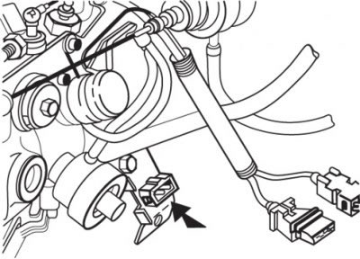
Pic. 4.12. Connector location (arrow) injector needle lift sensor
4. Disconnect the connector from the injector needle lift sensor (pic. 4.12).
5. Remove fuel return hoses and plug all connections.
6. Using the special tool MB996041, unscrew the injectors.
7. Remove the heat shield.
8. Close the nozzle holes with a clean rag and after turning the crankshaft with a starter, check for foreign particles on it.
Attention! Keep clear of the injector holes while cranking the crankshaft with the starter.
Attention! If coolant, oil, fuel, etc. got into the cylinder during compression measurement. (as a result of cracks), then these substances will heat up and splash out under pressure from the hole, which is very dangerous.
9. Install the heat shield and O-ring on the cylinder head.
10. Install and secure a compression gauge for measuring compression in diesel engines.
11. Turning the crankshaft of the engine with a starter, measure the compression in each cylinder, which must be at least 2000 kPa.
12. After measuring the compression in all cylinders, check that the compression difference between the cylinders is no more than 400 kPa.
13. If in any cylinder the compression exceeds the maximum allowable value or the difference in compression between the cylinders exceeds the maximum allowable value, then fill in a little engine oil into the nozzle hole of this cylinder and repeat the measurements.
14. If after oil filling the compression has increased, then the causes of the malfunction are wear or damage to the piston ring and / or cylinder mirror.
15. If the compression does not increase after filling with oil, then either the valve seat is burnt or damaged, or a gas leak has occurred (pressure) through the cylinder head gasket.
16. Remove the compression gauge.
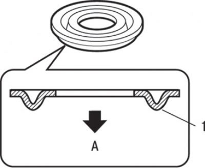
Pic. 4.13. The position of the thermal pad before installing the injector: And – the party of a head of the block of cylinders; 1 - bead of thermal thermal pad
17. Install a new thermal pad in the cylinder head with the shoulder towards the swirl chamber (pic. 4.13).
18. Using a special tool, tighten the nozzles to 70 Nm.
19. Reinstall the fuel return hoses.
20. Connect the connector to the injector needle lift sensor.
21. Connect the high pressure fuel lines.
22. Connect the solenoid fuel shut-off valve connector (immobilizer).
23. If the check engine light is flashing, clear the DTCs using the MUT-II.