



Contents: Examination ⤓ Adjustment ⤓
Examination
1. Checking and adjusting valve clearances must be carried out on a cold engine.
2. Remove the cylinder head cover.
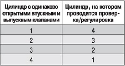
3. Check and adjust the valve drive clearances in the following sequence. Identify a cylinder with equally open intake and exhaust valves and check the valve clearances on the cylinder with equally closed intake and exhaust valves (see Table 4.1).
Table 4.1. Cylinder number on which the check/adjustment is carried out depending on the cylinder number with equally open intake and exhaust valves
4. Turn the engine crankshaft by the crankshaft pulley mounting bolt by a quarter of a turn and take the following measurement.
5. Using a feeler gauge blade, measure the valve drive clearance. When measuring the clearance, the feeler blade should move very tightly.
6. Nominal clearance (cold engine):
- inlet valve 0.15-0.25 mm;
- outlet valve 0.35–0.45 mm.
7. If the gap value does not fit within the specified limits, adjust the gap by selecting adjusting washers of the required thickness, performing the following operations.
Adjustment
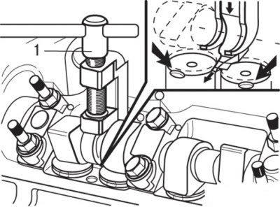
Fig. 4.3. Using a special tool (1) to adjust the valve drive clearance
1. Unscrew the base of special tool 1 (Fig. 4.3) by 6 mm.
2. Move the pusher slots to the position shown in Fig. 4.3.
3. Place the special tool with its base in the slots of the pushers, and then push the special tool forward as far as possible.
4. Press the plungers in.
Caution! When replacing the adjusting washers, the piston should not be at TDC. Turn the crankshaft so that the piston is slightly after TDC, otherwise, when pressing the tappets, the valves may hit the pistons.
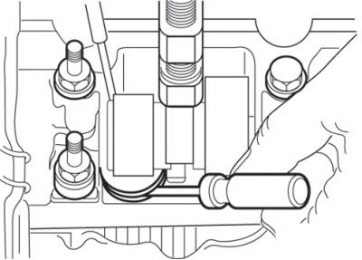
Fig. 4.4 Using a thin screwdriver to remove the adjusting washer
5. Using a thin screwdriver, remove the adjusting washer (Fig. 4.4).
6. Select a shim of the required thickness that provides the nominal clearance.
7. Nominal clearance (cold engine):
- inlet valve 0.20 mm;
- outlet valve 0.40 mm.
Example.
If the measured gap is 0.25 mm, and the required gap should be 0.40 mm, then the old adjusting washer should be replaced with another one, the thickness of which is 0.15 mm less.
[The material was created based on the website MITSUBISHIMAN]
Caution! Measure the thickness of the adjusting shim with a micrometer. Always use new adjusting shims.
The thickness of the adjusting washers in the range from 3.25 to 4.25 mm changes in 0.05 mm increments, in the range from 4.30 to 4.50 mm in 0.10 mm increments.
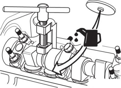
Fig. 4.5. Installing the adjusting washer in place (the protruding part should be directed towards the pusher)
8. Before installation, the adjusting washer must be lubricated with engine oil and installed in place with the protruding part towards the pusher (Fig. 4.5).