
Setting the stator and rotor of the sensor when measuring the gap
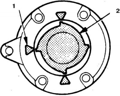
1. Stator
2. Rotor
Check the gap between the stator and the rotor with a non-magnetic feeler gauge, which should be 0.2 mm.
Valves are regulated only on diesel engines, other engines are equipped with hydraulic pushers. Some of the engines are also provided with additional injection jet valves, which require adjustment according to a special technique.
The clearances of the intake and exhaust valves on a warm engine are 0.25 mm.
Diesel 2.3 l
Adjustment
1. Warm up the engine.
2. Stop the engine and turn off the ignition.
3. Set the piston of the 1st cylinder to the TDC of the compression stroke. To do this, turn the crankshaft clockwise until the mark on the pulley or damper aligns with the lug on the cylinder block. Remove the valve cover and check the valve springs of the 1st cylinder. If both springs or at least one are compressed, then turn the crankshaft 1 turn. If the rocker arms sway, then the piston of the 1st cylinder is at TDC of the compression stroke.
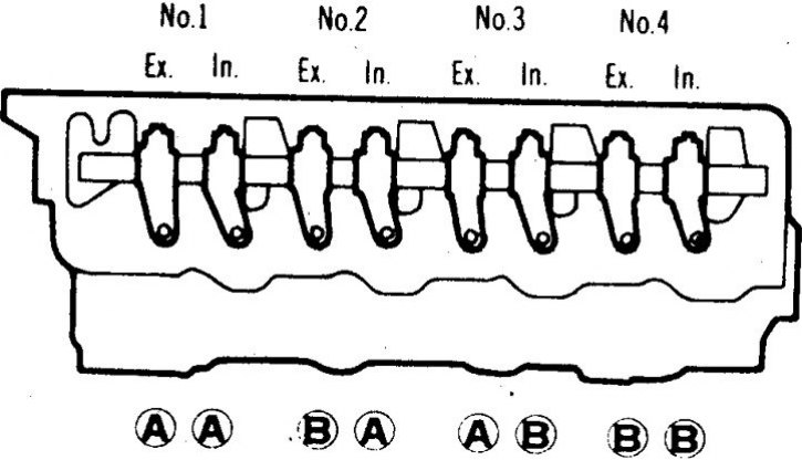
4. Loosen lock nuts A.
5. Set the gap to 0.25 mm and tighten the lock nut.
6. Set the piston of the 4th cylinder to the TDC of the compression stroke and adjust the clearances in the valves B.
7. Install the removed parts.
8. Check up turns of idling.
2.0 and 2.6L engines
On these engines, only the valves of the fuel jets of the combustion chamber are regulated.
1. Warm up the engine.
2. Stop the engine and turn off the ignition.
3. Check the torque of the cylinder head bolts (see subsection 3.5.6).
4. Set the piston of the 1st cylinder to the TDC of the compression stroke. To do this, turn the crankshaft clockwise until the mark on the pulley or damper aligns with the lug on the cylinder block. Remove the valve cover and check the valve springs of the 1st cylinder. If both springs or at least one are compressed, then turn the crankshaft 1 turn. If the rocker arms sway, then the piston of the 1st cylinder is at TDC of the compression stroke.
5. Loosen the jet valve locknut and turn the screw to set the gap to 0.25 mm (the probe should slide with little effort). Tighten locknut.
6. Adjust the valve clearances of the remaining cylinders, in accordance with the order of operation of the engine.
7. Install the removed parts.
8. Check up turns of idling.
Engines 2.4, 3.0 and 3.5 liters
The valve clearances of these engines are set only when repairing the cylinder head (see subsection 3.5.6 and subsection 3.4.24).