



Contents: Engines 2.0 and 2.6 l ⤓ Engines 2.4 and 3.0 l (12-valve) ⤓ Engine 3.0 l (24-valve) and 3.5 l ⤓
As a rule, this operation is performed during each cycle of engine adjustment work. The ignition timing is very stable when using automatic adjustment, however, the manufacturer allows a deviation from the optimal setting of (±2)°.
It is recommended to adjust idle speed and ignition timing together with subsequent mutual adjustment. When setting the ignition, first of all, follow the data on the underhood plate.
Engines 2.0 and 2.6 l
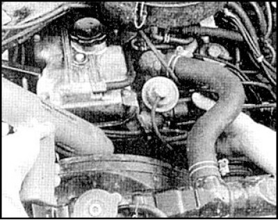
Adjusting the ignition sensor on a 2.0L engine
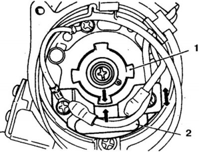
1. Rotor
2. Ignition unit
1. Warm up the engine.
2. Turn off all consumers, set the transmission to neutral position.
3. Connect the tachometer according to the manufacturer's instructions and check the idle speed.
4. Connect the strobe light according to the manufacturer's instructions.
5. Start the engine and point the light at the crankshaft pulley. At idle, the illuminated mark should be opposite the scale pointer on the front cover.
If adjustment is necessary, loosen the bolt and turn the distributor housing until the mark aligns with the pointer. Tighten the bolts and recheck the ignition timing.
6. Stop the engine and disconnect the strobe light.
Engines 2.4 and 3.0 l (12-valve)
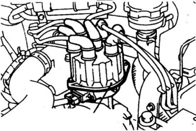
Crankshaft speed sensor on a 3.0L engine
Crankshaft rotation sensor connection diagram (12-valve 3.0L engine)
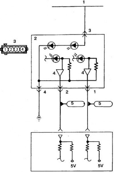
1. Injection relay; 2. Distributor; 3. Connector on the test device side; 4. Crankshaft speed sensor; 5. Processor unit
1. Warm up the engine. Turn off all consumers, set the transmission to neutral position.
2. Stop the engine and connect the strobe light according to the manufacturer's instructions.
3. Connect the engine speed sensor connector contacts with staples (or filters, depending on the engine) and wires from the primary winding of the coil.
Connect the tachometer to the paper clip without disconnecting the connector.
4. Start the engine and check the idle speed.
5. Stop the engine and turn off the ignition.
6. Connect the ignition switch terminal to ground.
7. Start the engine.
8. Point the strobe light at the crankshaft pulley. At idle, the ignition timing should be 3–7° before TDC.
9. If adjustment is necessary, loosen the fastening nut, turn the distributor housing and set the ignition timing. Tighten the nut carefully.
10. Stop the engine and remove the paper clip and ground jumper.
11. Start the engine and check the ignition timing again. The ignition timing should be 8° BTDC on a 2.4L engine and 15° BTDC on a 3.0L engine.
A slight difference from these values is allowed, which may be due to the processor mode during the basic ignition setup.
Engine 3.0 l (24-valve) and 3.5 l
Crankshaft rotation sensor connection diagram (24-valve 3.0L engine and 2-shaft 3.5L engine)
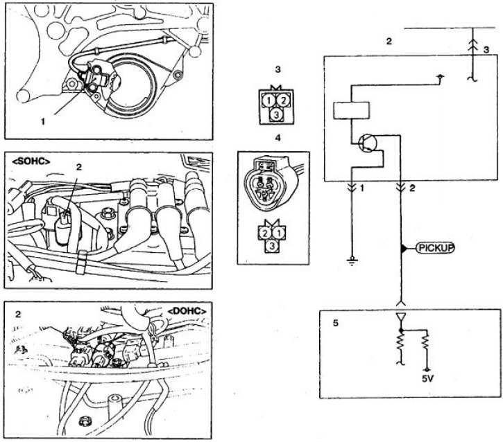
1. Crankshaft speed sensor; 2. Sensor connector; 3. Connector on the test device side; 4. Connector on the wiring side; 5. Processor unit
1. Warm up the engine. Turn off all consumers, set the transmission to neutral position.
2. Stop the engine and connect the strobe light according to the manufacturer's instructions.
3. Aim the strobe light at the crankshaft pulley. At idle, the ignition timing should be 2–8° BTDC.
4. Start the engine and check the idle speed, which should be 600-800 rpm. Adjust if necessary.
5. Stop the engine and turn off the ignition.
6. Connect the ignition switch terminal to ground.
7. Start the engine.
8. Point the strobe light at the crankshaft pulley. At idle, the ignition timing should be 2–8° before TDC.
9. If necessary, adjust the position of the crankshaft speed sensor.
10. Stop the engine and remove the paper clip and ground jumper.
11. Start the engine and check the ignition timing again. The ignition timing should be 15° BTDC for both engines. A slight difference from these values is allowed, which may be due to the processor mode during the basic ignition setup.