



2. Disconnect the 2-pin connector from the ignition distributor, connect the special tool (test wire harness MB 991348) to it. All terminals must be connected.
3. Connect the tachometer to terminal "12" of the distributor connector.
Warning! Do not use MUT-II. If you connect it to the diagnostic connector, it will show the current ignition timing, not the base one.
4. Install the strobe light in accordance with its operating instructions.
5. Start the engine and let it idle.
6. Check the idle speed, which should correspond to the nominal value.
7. Turn off the ignition.
8. Remove the waterproof plug from the brown colored connector of the base ignition timing adjustment.
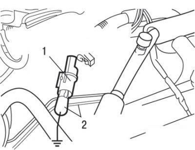
Fig. 3.5. Using a wire with an alligator clip connector to connect the connector terminal to ground when adjusting the base advance angle: 1 – brown connector for adjusting the basic ignition timing angle; 2 – wire with crocodile clip
9. Using a wire with an alligator clip, connect the terminal of the base advance angle adjustment connector to ground (Fig. 3.5).
Caution! Connecting this connector to ground switches the engine to the base ignition timing mode.
10. Start the engine and let it idle.
11. Check the value of the basic ignition timing angle, which should be within 5° ±2° before TDC.
12. If the value of the basic ignition timing angle does not correspond to the nominal value, loosen the ignition distributor mounting bolt and adjust the ignition timing angle by turning the distributor housing.
13. After adjustment, tighten the distributor mounting bolt to 24 N·m.
14. Stop the engine, disconnect the alligator clip from the ignition timing adjustment connector terminal and insert a waterproof plug into the connector.
15. Start the engine and check the ignition timing, which should be 10° before TDC.
Attention! Even in normal engine operation mode, the ignition timing angle varies within ±7°.
As the altitude increases, the advance angle automatically increases by approximately 5° from the nominal value of 10° BTDC.