
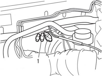
Pic. 3.6. Connector location (1) tachometer
2. Insert a paper clip from the side of the wires into the one-pin connector of the tachometer, as shown in fig. 3.6.
3. Connect the test lead of the tachometer to remove voltage from the primary circuit to the paper clip installed in the connector.
Attention! Do not use MUT-II. If you connect it to the diagnostic socket, it will show the current ignition timing, not the basic ignition timing.
4. Install the stroboscope in accordance with its instruction manual.
5. Start the engine and let it idle.
6. Check the idle speed, which should be (800±100) min-1.
7. Turn off the ignition.
8. Remove the waterproof plug from the brown base ignition timing connector.
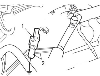
Pic. 3.5. Use of wire with connector type «crocodile» to connect the output of the connector with «weight» when adjusting the basic lead angle: 1 - brown connector for adjusting the basic ignition timing; 2 - wire with clamp type «crocodile»
9. With wire connector type «crocodile» connect the lead of the basic lead adjustment connector to «weight» (see fig. 3.5).
Attention! Connection with «weight» this connector puts the engine into basic ignition timing.
10. Start the engine and let it idle.
11. Check the value of the basic ignition timing, which should be within 5°± 3°before TDC.
12. If the basic ignition timing does not correspond to the nominal value, check the condition of the multipoint fuel injection system (MPI).
13. Stop the engine, disconnect the type connector «crocodile» wire from the ignition timing adjustment connector terminal and insert the waterproof plug into the connector.
14. Start the engine and check the ignition timing, which should be equal to 8°before TDC.
Attention! Even during normal engine operation, the ignition timing changes within±7°.
Attention! As the altitude increases, the lead angle automatically increases by approximately 5°above the nominal value of 8°before TDC.