
Removing
1. Disconnect a wire from the negative plug of the storage battery.
2. Remove the protective cover.
3. Drain the coolant from the engine cooling system.
4. Remove the air inlet hose.
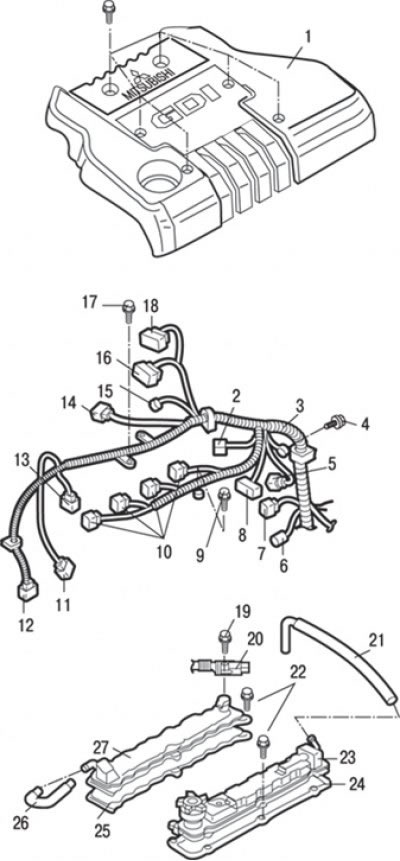
Pic. 3.21. Cylinder head covers: 1 - engine cover; 2 - connector for a combination of control wiring harness and injector wiring harness; 3 – a plait of wires of management; 4 - bolt, 5.0 Nm; 5 – a socket of the gauge of provision of a camshaft; 6 – a socket of the gauge-pointer of temperature of a cooling liquid of the engine; 7 – a socket of the gauge of temperature of a cooling liquid of the engine; 8 – a socket of the gauge of malfunction of system of ignition; 9 - bolt, 11 Nm; 10 - ignition coil connectors; 11 - connector of the front oxygen concentration sensor; 12 – a socket of the gauge of provision of a cranked shaft; 13 - fuel pressure sensor; 14 – a socket of a combination of a plait of wires of management and a plait of wires of system recirculation of the fulfilled gases (EGR); 15 - connector for the canister purge solenoid valve; 16 - connector throttle position sensor; 17 - bolt, 7.0 Nm; 18 - throttle control servo connector; 19 - bolt, 10–12 Nm; 20 - connector bracket (injector wiring harness); 21 - forced crankcase ventilation hose; 22 - bolts, 3–4 Nm; 23 – a cover of a head of the block of cylinders (from the exhaust valves); 24 – a lining of a cover of a head of the block of cylinders; 25 – a lining of a cover of a head of the block of cylinders; 26 - positive crankcase ventilation hose (PCV); 27 – a cover of a head of the block of cylinders (from intake valves)
5. Turn away bolts and remove a cover 1 (pic. 3.21) engine.
6. Disconnect a socket 12 of the gauge of position of a cranked shaft.
7. Disconnect the fuel pressure sensor connectors 13, front oxygen sensor 11, control harness combination and EGR harness (EGR) 14, canister purge solenoid valve 15, throttle position sensor 16, throttle control servo 18, control harness and injector harness combination 2, ignition coil 10, ignition system fault sensor 8, camshaft position sensor 5, coolant temperature sensor engine 7 and engine coolant temperature gauge 6.
8. Turn away bolts and remove a plait of 3 wires of management.
9. Disconnect hose 26 crankcase ventilation (PCV).
10. Disconnect the hose 21 forced crankcase ventilation.
11. Remove the ignition coil.
12. Remove the intake manifold.
13. Remove the timing belt.
14. Turn away a bolt and remove an arm 20 of a socket (injector wiring harness).
15. Turn away bolts and remove a cover 27 of a head of the block of cylinders (from intake valves) and padding.
16. Turn away bolts and remove a cover 23 of a head of the block of cylinders (from the exhaust valves) and padding.
17. Using a special tool, fix the camshaft pulley from turning, unscrew the bolt and remove the camshaft pulley.
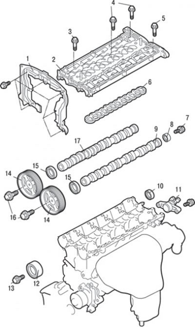
Pic. 3.22. Camshafts and camshaft seals: 1 - rear upper casing of the timing belt; 2 – a cover of bearings of camshafts; 3 - bolt, 10–12 Nm; 4 - bolts, 21–25 Nm; 5 - bolt, 21–25 Nm; 6 – laying of a cover of bearings of camshafts; 7 - bolt, 22 Nm; 8 - cylinder of the camshaft position sensor; 9 – a camshaft of final valves; 10 - plug; 11 - support for the camshaft position sensor; 12 - idle (guide) pulley/roller; 13 - bolt, 35 Nm; 14 - camshaft pulley; 15 – an epiploon of a camshaft; 16 - bolt, 88 Nm; 17 - intake camshaft
18. Turn away a bolt and remove idle (guide) pulley/roller 12 (pic. 3.22).
19. Turn away bolts and remove a back top casing 1 of a timing belt.
20. Remove the camshaft seal 15.
21. Turn away a bolt and remove a support 11 of the gauge of provision of a camshaft.
22. Remove plug 10.
23. Remove the high pressure fuel pump assembly.
24. Evenly and gradually unscrew the bolts securing the cover 2 of the camshafts and remove it.
25. Remove a lining 6 of a cover of bearings of camshafts.
26. Remove the camshaft 17 inlet valves.
27. Remove the camshaft 9 exhaust valves.
28. Turn away a bolt and remove the cylinder 8 of the gauge of position of a camshaft.
Installation
Installation is carried out in the reverse order of removal, taking into account the following.
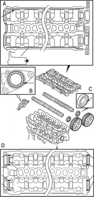
Pic. 3.23. Lubrication points (engine oil) and sealant when installing camshafts in the cylinder head: A - bottom view of the camshaft bearing cap and the place where sealant 3M ATD Part No. 8660 or similar is applied; B - support for the camshaft position sensor and the place where the sealant is applied MITSUBISHI GENUINE PART MD970389 or similar; C - front camshaft seal and engine oil lubrication points; D - top view of the cylinder head and the place of application of sealant 3M ATD Part No. 8660 or equivalent
1. Apply engine oil to all moving parts before installation (pic. 3.23).
2. Lubricate the cams and camshaft journals with engine oil.
3. Install the camshafts on the cylinder head.
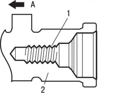
Pic. 3.24. Bolt hole location (1) in the camshaft (2) from the exhaust valves: A - side of the camshaft pulley
Attention! Be careful not to mix up the intake and exhaust camshafts. On the camshaft on the exhaust side there is a hole for the camshaft position sensor cylinder bolt (pic. 3.24).
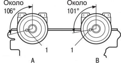
Pic. 3.25. Installing the camshaft pins: And – the party of inlet valves; B - the side of the exhaust valves; 1 - pin
4. Install the camshaft pins as shown in fig. 3.25.
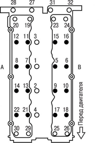
Pic. 3.26. The sequence of tightening the bolts of the camshaft bearing cover: And – the party of inlet valves; B - side of the exhaust valves
5. Tighten bolts of fastening of a cover of bearings of camshafts the set moments in the sequence shown in fig. 3.26.
Tightening torques:
- bolts marked with a black dot, 10–12 Nm;
- bolts marked with a white dot, 21–25 Nm.
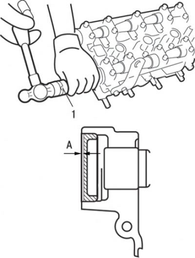
Pic. 3.27. Using a special tool for pressing the plug: 1 - special tool MD998762; A - pressing depth 2 mm
6. Use the special tool to press the plug (pic. 3.27).
7. Grease an internal circle of a working edge of an epiploon with engine oil.
8. Press in the stuffing box.
9. To fix the camshaft pulley, use the same special tool as when removing, and tighten the mounting bolt.
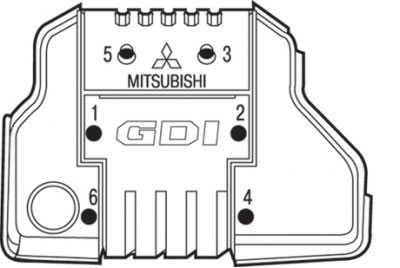
Pic. 3.28. Engine cover bolt tightening sequence
10. Install the engine cover and temporarily tighten the mounting bolts in the sequence shown in fig. 3.28 so that the lid can be easily moved by hand.
11. Tighten the mounting bolts to 3.0 Nm in the sequence shown in fig. 3.28.
12. Purge the high pressure fuel passage.
13. Check for fuel leaks.
14. Install the protective cover.
15. Fill in cooling liquid in the engine cooling system.
16. Install the air inlet hose.