
Removing
1. Disconnect a wire from the negative plug of the storage battery.
2. Remove the fuel pressure in the power supply system.
3. Drain the coolant from the engine cooling system.
4. Remove the air intake hose.
5. Remove the timing belt.
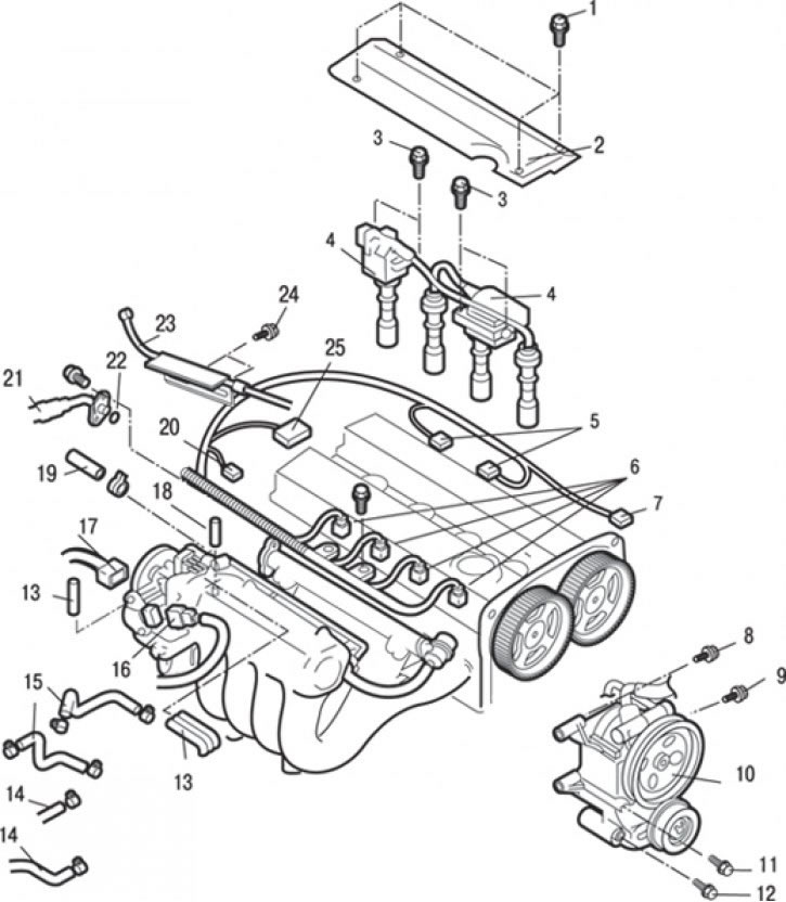
Pic. 3.45. Connecting connectors and hoses to the cylinder head of a DOHC engine: 1 - bolt, 3.0 Nm; 2 - central cover; 3 - bolt, 10 Nm; 4 - ignition coil assembly; 5 - connectors of the ignition coil; 6 – injector connectors; 7 – a socket of the gauge of provision of a camshaft; 8 - bolt, 22 Nm; 9 - bolt, 44 Nm; 10 - power steering pump with bracket assembly; 11 - bolt, 49 Nm; 12 - bolt, 44 Nm; 13 – connection of vacuum hoses; 14 – connection of heater hoses; 15 – connections of hoses of system of cooling; 16 - throttle position sensor connector (TPS); 17 – a socket of a regulator of frequency of rotation of idling; 18 – connection of a vacuum hose of the amplifier of brakes; 19 – connection of a hose of return of fuel; 20 – a socket of the gauge-switch of pressure of oil; 21 - high pressure fuel hose connection; 22 - an annular sealing gasket; 23 – accelerator pedal cable connection; 24 - bolt, 10 Nm; 25 – a socket of the gauge of malfunction of system of ignition
6. Turn away bolts and disconnect a cable 23 (pic. 3.45) accelerator pedal.
7. Turn away bolts and remove the central cover 2.
8. Disconnect sockets 5 ignition coils.
9. Turn away bolts and remove coils 4 ignitions in gathering.
10. Disconnect the throttle position sensor electrical connectors (TPS) 16, idle speed controller 17, oil pressure switch 20, ignition system malfunction sensor 25, injectors 6 and camshaft position sensor 7.
11. Loosen the clamp and disconnect the fuel return hose 19.
12. Turn away bolts, disconnect a fuel hose of a high pressure and remove an annular sealing lining 22.
13. Disconnect the hose 18 of the vacuum brake booster.
14. Disconnect the vacuum hose 13.
15. Loosen the clamps and disconnect the hoses 15 of the cooling system.
16. Loosen the clamps and disconnect the heater hoses 14.
17. Turn away bolts and remove an arm and knot 10 of the pump of the power steering in gathering together with the hoses connected to it.
18. Tie the removed power steering pump assembly with bracket and hoses with wire and place so that it does not interfere with the removal and installation of the cylinder head assembly.
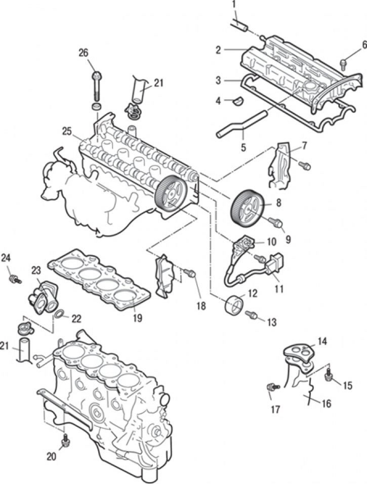
Pic. 3.46. Cylinder head gasket for DOHC engines: 1 - forced crankcase ventilation hose; 2 – a cover of a head of the block of cylinders; 3 – a lining of a cover of a head of the block of cylinders; 4 - semicircular plug; 5 - crankcase ventilation hose (PCV); 6 - bolt, 3.4 Nm; 7 - rear timing belt cover; 8 - camshaft pulley (exhaust valve drive); 9 - bolt, 88 Nm; 10 - camshaft position sensor; 11 - bolt, 8.8 Nm; 12 - idle (guide) video clip; 13 - bolt, 35 Nm; 14 - gasket; 15 - bolt, 49 Nm; 16 – a reception pipe of system of release of the fulfilled gases; 17 - bolt, 50 Nm; 18 - bolt, 10–12 Nm; 19 – laying of a head of the block of cylinders; 20 - bolt, 26–33 Nm; 21 – connection of a hose of a radiator; 22 - an annular sealing gasket; 23 - inlet pipe of the cooling system and thermostat housing as an assembly; 24 - bolt, 22–25 Nm; 25 – a head of the block of cylinders in gathering; 26 – a bolt of fastening of a head of the block of cylinders, 78 Nm + 0 Nm + 20 Nm + 90°+ 90°
19. Loosen the clamp and disconnect the radiator hose 21 (pic. 3.46).
20. Unscrew the bolts and remove the inlet pipe 23 of the cooling system, the thermostat housing assembly and the O-ring 22.
21. Disconnect the hose 1 of the forced ventilation of the crankcase and the hose 5 of the exhaust gases (PCV).
22. Turn away bolts and remove a cover 2 of a head of the block of cylinders and a lining 3.
23. Remove the semicircular plug 4.
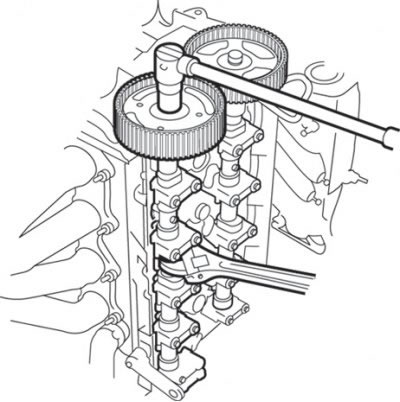
Pic. 3.16. Unscrewing the bolt securing the camshaft pulley
24. Holding the camshaft hex area with a wrench, unscrew the bolt securing the camshaft pulley (see fig. 3.16).
Attention! To avoid breaking the pulley, do not hold the camshaft pulley from turning with a wrench.
20. Remove pulley 8 of the exhaust camshaft.
21. Turn away a bolt and remove idle (guide) roller 12.
22. Turn away a bolt and remove the gauge 10 of provision of a camshaft.
23. Remove the bolts and remove the rear cover 7 of the timing belt.
24. Turn away nuts and remove a reception pipe 16 and a lining 14 of system of release of the fulfilled gases.
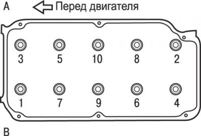
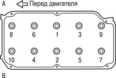
Pic. 3.40. The sequence of reversing the cylinder head bolts: And – the party of inlet valves; B - side of the exhaust valves
25. Turn away bolts of fastening of a head of the block of cylinders 26 in 2 or 3 stages in the sequence shown in fig. 3.40, and then remove the cylinder head assembly.
26. Remove the gasket 19 of the cylinder head.
Preparing for installation
Cm. «SOHC Engine Cylinder Head Gasket».
Installation
Installation is carried out in the reverse order of removal, taking into account the following.
1. Degrease mating surfaces of the gasket.
2. Check up coincidence of all openings on a lining and a head of the block of cylinders.
3. Before installing the bolts, measure the shank length of the bolt (up to the head), which should be no more than 96.4 mm. If this value is exceeded, the bolt must be replaced.
4. Bolt washer should be installed with the chamfered surface of the washer on top.
5. Before installation, it is necessary to lubricate the upper surface of the washer and the thread of the bolt with a small amount of engine oil.
Pic. 3.41. The sequence of screwing in the cylinder head bolts: And – the party of inlet valves; B - side of the exhaust valves
6. Tighten bolts of fastening of a head of the block of cylinders in several stages in the sequence shown in fig. 3.41.
Bolt tightening steps:
- 1st - tighten with a torque of 78 Nm;
- 2nd - completely loosen all bolts in the reverse order shown in fig. 3.41;
- 3rd - tighten with a torque of 20 Nm;
- 4th - tighten the bolts at an angle of 90°. Apply paint marks on the bolt heads and cylinder head;
- 5th - turn the bolts another 90°. The marks on the bolts and the cylinder head must be in line.
Attention! Always tighten the bolt to a strict 90°angle. Otherwise, the cylinder head bolt may be loosened (the reliability of the gas joint will not be ensured).
If the bolt is turned more than 90°, loosen it completely and repeat all bolt tightening operations.
7. When installing the exhaust camshaft pulley, fix the pulley from turning with a special tool, as when removing it, and tighten the pulley mounting bolt to 38 Nm.
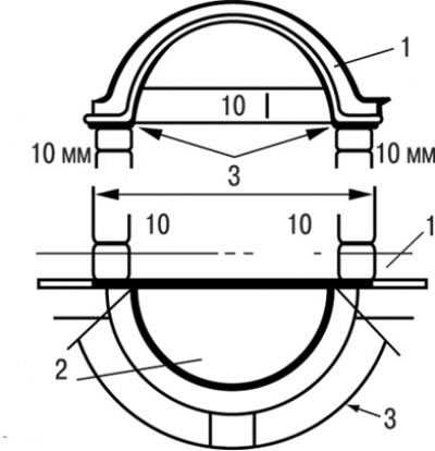
Pic. 3.47. Places for applying sealant 3M ATD Part No. 8660 before installing the cylinder head cover gasket: 1 – a lining of a cover of a head of the block of cylinders; 2 - semicircular plug; 3 - places for applying sealant
8. Before installing the cylinder head cover gasket, apply 3M ATD Part No. 8660 sealant or similar to the locations shown in fig. 3.47.
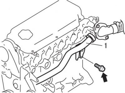
Pic. 3.42. Location of the inlet pipe bolt (1) cooling systems
9. At installation of an inlet pipe of system of cooling loosen a bolt of fastening of an inlet pipe, as is shown in fig. 3.42.
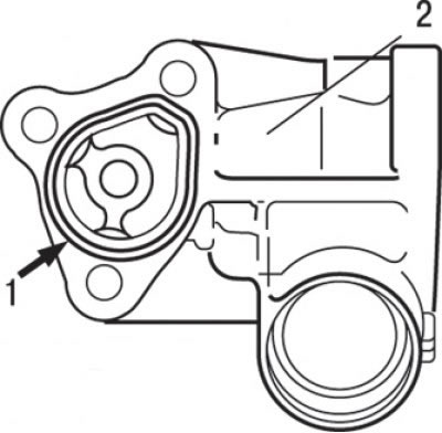
Pic. 3.43. Place of application (1) sealant in the form of a roller with a diameter of 3±0.5 mm Mitsubishi Genuine Part MD970389 or similar on the mating surface of the inlet pipe (2)
10. When installing the inlet and thermostat assembly, apply a bead of sealant to the mating surface of the inlet (see fig. 3.43).
11. Moisten the O-ring of the cooling system supply pipe with water and insert the thermostat housing into the cooling system supply pipe.
12. Tighten bolts of fastening of the case of the thermostat in gathering.
13. Tighten a bolt of fastening of a bringing pipe of system of cooling.
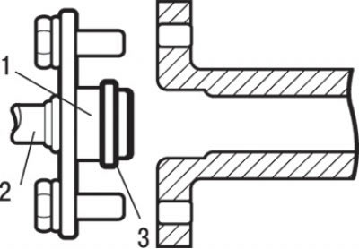
Pic. 3.44. High pressure fuel hose installation: 1 - place of lubrication with engine oil; 2 - high pressure fuel hose; 3 - ring gasket
14. When installing the high pressure fuel hose, lubricate the O-ring with a small amount of clean engine oil (see fig. 3.44).
Attention! Do not allow oil to enter the fuel rail.
15. Slightly turning the fuel hose flange to the right and left, carefully insert it into the fuel rail to prevent damage to the O-ring. After installation, check that the hose turns smoothly in the fuel rail.
16. If the hose flange sticks when turning, the O-ring may be damaged. Detach the flange (complete with hose) from the fuel rail and inspect the gasket for damage, then reinsert it and check for smooth turning.
17. Tighten the mounting bolts.
18. Install the timing belt.
19. Install the air intake hose.
20. Fill in cooling liquid in the cooling system.
21. Adjust the accelerator pedal cable.