
General information
Modern car engines use one of two types of cylinder heads: overhead valves (OHV) and with an overhead camshaft (OHC). The last type can be broken down into a sub-group sensor-switch: with one overhead camshaft (SOHC, or just OHC) and with two overhead camshafts (DOHC).
Currently, cylinder heads are made by casting from aluminum alloy, which can significantly reduce the total power unit while maintaining such vital properties as reliability and heat dissipation.
In fairness, it should be noted that along with aluminum in the manufacture of cylinder heads, traditional cast iron is also quite widespread. Regardless of the material, all heads are equipped with valve seats. Some heads have two valves per cylinder, although more recently the multi-valve configuration has become more common, where each cylinder can be equipped with three, four or even five valves. Fine mechanical grinding of the working chamfers of the plates to the seats ensures the tightness of the combustion chambers in the closed position of the valves. The use of guide bushings ensures the uniqueness of the reciprocating movement of the valves and the alignment of the latter relative to the seats. In view of the foregoing, the clearance of the valve stem in the guide sleeve acquires a critical value. Excessive clearances typically increase engine oil consumption, vacuum losses can occur, and valve seat damage is more likely. Too tight fit of the valves in the guide bushings is fraught with their biting, which leads to an inevitable decrease in the power developed by the power unit and an increased risk of engine jamming. In addition to the guide bushings, the valves are also necessarily equipped with springs that provide the necessary tightness of pressing the plates to the seats and return them to the closed position after being forced to open under the influence of the force developed by the camshaft eccentric cams (ov). To fix the springs on the valve stems, special plates and two-section split locks are used (crackers). In heads made of aluminum alloy, special adjusting washers are installed on the valve springs to protect the latter from wiping.
Ideally, during the course of the capital (restorative) repair of the cylinder head, all valves must be replaced complete with springs and guide bushings. However, depending on the condition of the engine being serviced, determined primarily by the conscientiousness of the vehicle owner, this replacement may not be necessary. The main cause of premature wear of the valve train components is the incorrect adjustment of the engine settings. So, prolonged operation of the unit on a re-enriched air-fuel mixture often leads to washing out of the oil from the guide bushings with gasoline. The over-depletion of the mixture leads to an excessive increase in the temperature of its combustion, which leads to burnout of the valve plates and their seats. The life span of valve springs is directly related to the driving style inherent in the driver of the vehicle - frequent over-revving of the engine inevitably leads to faster failure of the springs.
Unfortunately, it is not possible to completely prevent wear on the internal components of the cylinder head. However, timely reconditioning with careful valve grinding will allow the vehicle owner to reduce material costs by extending the life of the cylinder head.
It should be noted that if only individual valves burn out, it would be reasonable to replace their entire set. This statement also applies to other components of the valve mechanism.
As unpleasant as it is, it is possible to determine the condition of the internal components of the cylinder head only after its preliminary disassembly. The description of procedure of dismantling of a head of cylinders on models of cars of the Mitsubishi brand Considered in the present Management is given below in this Section.
Cleaning
1. A thorough cleaning of the cylinder head and valve train components, followed by a detailed inspection of their condition, will help determine the approximate amount of restoration work to be done.
Note. Severe overheating of the engine can lead to deformation of the cylinder head and violation of the flatness of its mating surfaces.
2. Scrape off all traces of the old gasket material and sealant from the mating planes of the cylinder head, intake manifold and exhaust manifold, - try not to damage the surfaces. The use of a special softener, which should be pre-soaked with adhering deposits, will greatly facilitate the work - ask in car accessories stores.
3. Remove all traces of scale from the walls of the water channels.
4. Thoroughly clean all accessible cavities and openings with a stiff wire brush. In case of severe contamination of the channels, head cleaning should be entrusted to specialists.
5. "Drive away" with a suitable tap for each of the bolt holes, removing corrosion products from the thread, traces of old sealant and restoring damaged turns. If you have access to a compressed air source, blow out the holes to remove chips and small debris.
Remember to wear protective goggles when using compressed air!
6. Use a wire brush to clean the threads of the intake manifold and exhaust manifold studs.
7. Wash the head with solvent and dry thoroughly. The use of compressed air will significantly reduce the drying time and will guarantee the quality of cleaning hard-to-reach cavities and holes.
Note. Various kinds of compositions for removing traces of soot, which greatly facilitate the cleaning procedure, can be purchased at many car accessories stores. Remember that these types of products are usually chemically aggressive and must be used with appropriate precautions - strictly follow the manufacturer's instructions, usually given on the container label.
8. Wash the valve lifters with solvent, then dry them thoroughly. The use of compressed air will greatly facilitate the procedure (don't forget to wear safety glasses).
Note. Pushers equipped with hydraulic correctors should be folded upside down in an oil bath. Remember that during assembly, all components must be installed strictly in their original places.
9. Wash in solvent and thoroughly dry the valve springs, their plates, seats and split lock crackers - try not to mix up the components.
10. Scrape off the bulk of deposits formed on the surfaces of the valves, then with a wire nozzle to an electric drill, finally clean the surfaces of the valve stems and plates - make sure that the valves are not mixed up.
Disassembly
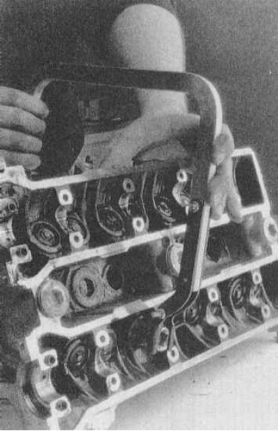
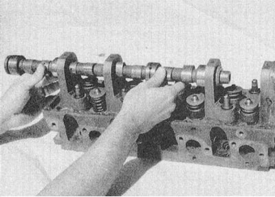
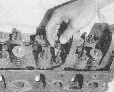
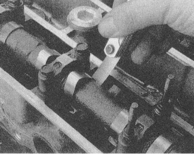
The design of the cylinder head used on a particular engine (SOHC or DOHC) does not have a fundamental effect on the procedure for dismantling the components of the valve drive mechanism. Examples of the appearance of cylinder heads are shown in the illustrations. It should only be noted that when disassembling a DOHC head, special attention should be paid to the thoroughness of the marking of all removed components - the intake valve drive components should not be confused with exhaust components during assembly if the cylinder number matches and almost absolute external identity. As a rule of thumb when marking parts, remember that the intake camshaft with associated components is located on the side of the intake pipe, the exhaust on the side of the exhaust manifold.
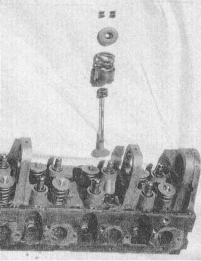 | 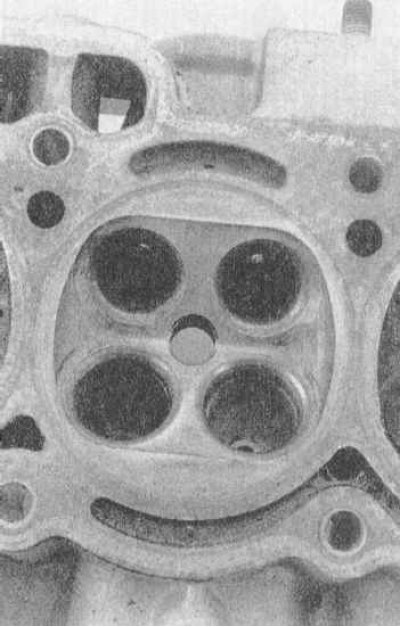 |
Heads with cup-type pushers
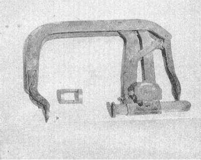
1. Most cylinder heads use cup-style tappets in the valve actuation mechanism. The crackers of the split valve spring lock are placed with this design inside the pusher socket. To disassemble this type of head, you will need a clamp-type valve spring compressor, a valve spring removal tool, and a small magnet to remove the split lock cotters.
2. If you have not already done this, remove the camshaft from the cylinder head (s) and/or valve lifters.
Note. Place removed components in clearly labeled plastic bags. Marking should guarantee the possibility of installing components during assembly strictly in their original places.
3. Turn the head over so that it is possible to install clamps on it to compress the valve springs - usually the head is laid horizontally with the gasket surface towards the performer and the valve springs away from it.
4. Putting the mandrel to extract the spring into the socket of the pusher, compress the spring.
5. Helping yourself with a screwdriver, use a small magnet to remove the split lock crackers from its seat.
6. Release the clamp and remove the valve spring.
7. Remove the valve from the cylinder head. If equipped, remove the oil seal.
Note. Special tools are available for removing oil seals. Alternatively, you can use ordinary needle nose pliers - try not to damage the walls of the pusher socket, which is fraught with a decrease in the adequacy of the fit of the latter.
8. With the appropriate configuration, remove the adjusting washer from the spring - use the magnet or a screwdriver again.
9. In the same manner, remove the remaining valve components. Remember that all components should be placed in clearly labeled containers or bags.
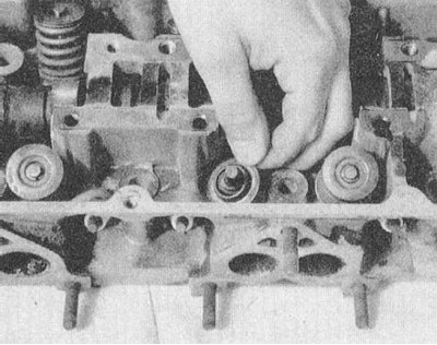
Heads with lever-type pushers
1. A special tool of standard type is usually used to compress the valve springs on heads of this type. However, on some models, there may not be enough free space to install such a tool - in such cases, you should use the clamp-type tool described above.
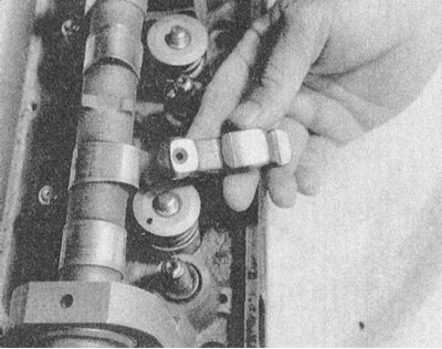
2. If not already done, remove the valve train components (valve actuation levers or rocker arms with their own axles) and remove the camshaft (s). If equipped, also remove the hydraulic valve clearance adjusters.
Note. All removable components should be folded in an organized manner, paying special attention to the clarity of the markings - when assembling, they must be installed strictly in their original places!
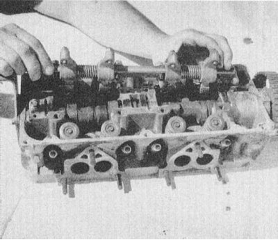 | 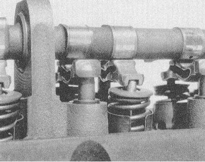 |
 |  |
3. Turn the head over so that there is free space for installing the valve spring compression tool.
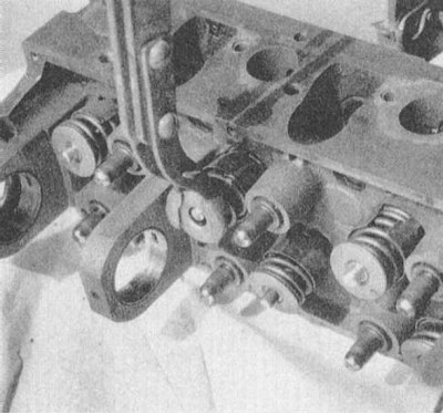
4. Having started the tool, compress the spring of the first valve, completely unloading its plate.
Note. Due to the development of carbon formation, the plate may "take a liking" to the crackers of the split lock and to release it, you will have to lightly tap it with a hammer.
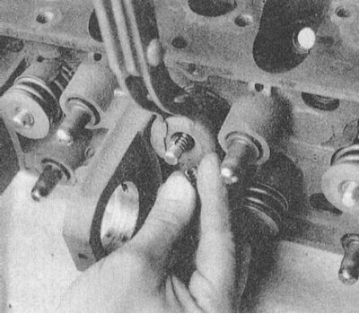
5. Use a small magnet to remove the split lock cotters from the groove on the valve stem.
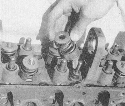
6. Release the tool and remove the poppet and spring from the valve stem.
7. If equipped, remove the oil seal.
Note. It is usually easier to remove the oil seal from the valve removed from the engine (see below).
8. Turn the head over so that the valve can be removed from it.
9. Remove the valve from the cylinder head.
Note. If necessary, pre-process the edges of the groove for the installation of crackers and the end of the valve shank with a fine-toothed file.
10. If equipped, remove the valve spring adjusting washer - use a magnet or a screwdriver.
11. In the same manner, remove the remaining valves from the head. Remember that all components should be placed in clearly labeled containers or bags.
Checking the Status of Components
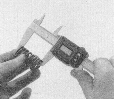
After thoroughly washing and drying the components of the valve mechanism removed from the head, you can begin to check their condition. Some control measurements will be required, for which you will need a micrometer with a jaw spread of 0 ÷ 25 mm, - for measuring the diameter of the valve stems, a plunger-type dial gauge / telescopic bore gauge, - for measuring the internal diameter of the guide bushings, a caliper and a special tool for assessing the degree of subsidence and correct alignment of the valve springs. In the absence of the listed tools at hand, checking the condition of the components should be entrusted to car service specialists.
Valves
1. Check the chamfers of the valve discs for cracks, cavities and signs of excessive wear. Traces of burning are most easily detected when examining the cylindrical part (girdle) dishes. The belt must be present on the plate without fail and have the same width around the entire perimeter of the valve. Rounding or melting of the edges of the belt indicates valve burnout. The degree of non-flatness of the end surface of the disc should also be assessed - if there is excessive deflection in its central part, the valve must be replaced (Preferably with others).
2. Next, you should check the condition of the valve stem shank, - carefully inspect its end face and the edges of the groove for installing split lock crackers, - make sure there are no burrs or burrs (especially if, when removing the valve, you had to resort to processing these areas with a file). The end of the valve stem must be absolutely flat, while some rounding always occurs with significant mileage of the unit. If necessary, restore the flatness of the end face by turning the valve.
3. Roll the valve stem on a flat surface (as such, window glass can serve), check it for signs of bending.
4. Finally, measure the diameter of the valve stem at several points with a micrometer. Compare the measurement results with each other - the rod must have a uniform thickness along its entire length. If the minimum tolerance of the valve stem diameter is not specified in the Specifications, a value of 0.025 mm should be taken as a guideline.
5. Defective or over-wear valves must be replaced (Preferably with others).
Valve springs, their holders and split lock crackers
1. First of all, check the valve springs for cracks, chips and other mechanical damage. Next, you should measure the free length of the springs - try not to confuse the intake valve springs with the exhaust springs. Compare the measurement results with the requirements of the Specifications.
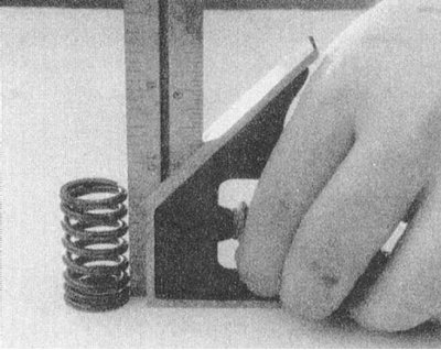
2. Using a ruler and a carpenter's angle, evaluate the adequacy of the trimming of each spring.
3. If you have a special device at hand, check the force developed by the springs. Compare the measurement results with the requirements of the Specifications.
4. Sagging, defective and excessively worn springs must be replaced (preferably as a whole set).
5. Spring plates rarely need to be replaced, however, evaluate the condition of their working surfaces in contact with the spring and split lock crackers. If there are signs of deformation or cracks, replace.
6. Assess the degree of wear of the internal and external working surfaces of split lock crackers. If necessary, crackers are replaced complete with their valve.
Cylinder head
When inspecting the cylinder head, special attention should be paid to the condition of the guide bushings and valve seats. You should also check the head casting for cracks and other mechanical damage and assess the degree of non-flatness of the mating surfaces.
Valve guides
1. After making sure that the condition of the valves is in good condition, the degree of wear of the guide bushings should be assessed by the size of the gaps in which the valve stems fit into them.
Note. It is preferable to replace the valves anyway.
2. Before starting measurements, carefully inspect the guide bushings for cracks, scuffs, burrs and other mechanical damage. When using removable bushings (on all heads made of aluminum alloy) evaluate the tightness of their fit - the presence of any slack is unacceptable. All bushings must protrude to the same height (counting from spring seats).
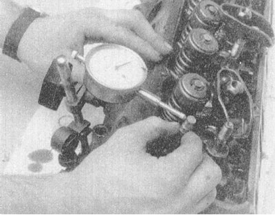
3. Attach a plunger-type dial gauge to the spring side of the cylinder head. Lightly grease the valve stem and thread it into place. Firmly press the meter plunger against the side surface of the valve stem in the shank area and zero the instrument. Pull the valve from side to side in the guide sleeve and read the meter reading - write down the result. Rotate the meter 90°from its original position and retest. Comparing the measurement results with each other, evaluate the ovality of the guide bushing. Also compare the results of both measurements with the requirements of the Specifications.
Note. Special telescopic bore gauges are available for determining the inner diameter of valve guides - when using this kind of instrument, compare the measurement results with the regulatory requirements given in the Specifications.
4. Worn or damaged guide bushings must be replaced or re-turned.
Valve seats
1. Perform a visual inspection of the valve seats. Pay attention to the presence of cracks, cavities and traces of burnout. Evaluate the depth of seating in the head by eye - excessive penetration indicates wear on the components. If cracks are found, the seats must be replaced.
2. If you have a special tool on hand, check the seats for signs of ovality. Compare the measurement results with the requirements of the Specifications, if necessary, make a groove.
Note. In the absence of standard values, the maximum allowable ovality of 0.051 mm should be considered.
Head flatness evaluation
1. Thoroughly clean the mating surfaces of the cylinder head, completely removing all traces of the old gasket material from them.
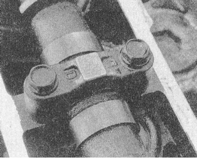
2. Flatness is checked using a special gauge and a blade-type feeler gauge. The measurement is made along the DP of the head and along both diagonals of the mating surface.
Note. A steel ruler placed on edge can be used as a flatness meter.
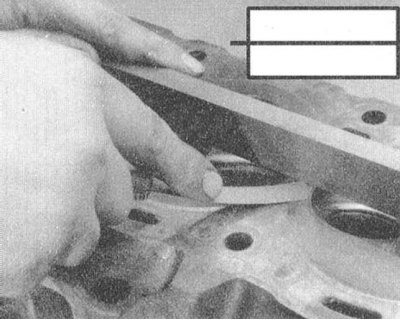 | 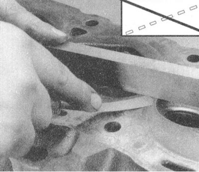 |
3. If the amount of flatness exceeds 0.076 mm over a length of 15.2 mm (or 0.152 mm for the full length of the mating surface), the cylinder head is subject to turning.
Note. After turning the cylinder heads of V-shaped engines, the landing flange of the inlet pipeline should also be machined accordingly in order to compensate for changes in the position of the mating surfaces.
Checking the condition of the head casting
1. Typically, cracks in the head casting appear in the area of \u200b\u200bthe combustion chambers, however, the possibility of their formation is also possible near the candle holes, valve seats and bearing surfaces of the valve drive levers.
2. Particular attention should be paid to checking the condition of the pouring in the area of the outlet ports.
3. It should be remembered that visual inspection does not reveal hidden casting defects. A much more detailed picture of the structure of the body of the head can be obtained during flaw detection using magnetic resonance methods (Magnaflux®), - for heads made of cast iron, or with the use of fluorescent compounds (Ziglo®), - for alloy heads. These kinds of checks can always be made for a very reasonable fee at service stations.
4. The head with mechanical damage must be replaced.
Camshafts and valve lifters
For a description of the procedures for checking the condition of the camshafts and components of the valve drive mechanism, see Section Removal and installation of camshafts and valve lifters.
Component Recovery Methods
Most of the restoration procedures should be carried out in a car service workshop.
Lapping of valves
Note. Lapping of valves is carried out last, after the condition of all head components has been checked and their necessary refurbishment / replacement has been carried out.
1. If the valves are found fit for further use, it is necessary to turn the end surfaces of their shanks and grind the working chamfers to their seats.
Note. New valves are also subject to lapping, after which they become rigidly attached to their seats.
2. Turn the cylinder head upside down.
3. Lightly lubricate the valve stems and thread them into their regular places in the head.
4. Lift the valve to be lapped off the seat and apply a little special lapping paste to the valve seat.
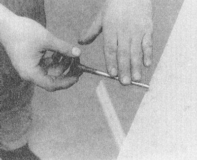
5. Lightly moisten the suction cup of the lapping holder and attach the lapping holder to the flat side of the valve disc.
6. Rotate the tool's drive handle between your palms and begin to lap the valve against your seat. Try to intercept the handle more often while slightly changing the position of the valve relative to the seat to avoid the formation of grooves.
7. Continue lapping until an even ring of dull gray color is formed on the working surface of the saddle of the same width around the entire perimeter.
8. Separate the actuator and proceed to grinding in the next valve.
9. Finally, be sure to thoroughly wipe the components, removing all traces of lapping paste and abrasive from their surface.
Springs, plates and crackers of split locks
10. The components listed in the heading of the subsection are not subject to refurbishment and, in case of their failure, must be replaced.
Valve guides
1. There are only two types of guide bushings used in automobile engines: removable (used in light alloy heads) and built-in (heads made of cast iron are used).
Note. Cast iron heads are sometimes also equipped with removable bushings.
2. Restoration of worn guide bushings can be done in one of four ways: knurling; installation of inserts; boring and replacement.
3. During knurling, the metal of the part is deformed, which leads to a decrease in the gap. At the same time, the centering of the bushing is restored. Knurling is the simplest and cheapest method of restoring guide bushings, however, it requires a special tool base and leads to a significant reduction in the service life of the restored part.
4. The bronze insert can be installed in a worn guide bush after it has been pre-bored. Threaded inserts are available, - for their installation, the sleeve must first be cut with a tap of the appropriate size. Alternatively, thin-walled split-type bushings can be installed - they are tucked into a bored bushing, after which they are flared with a special tool and machined to the desired size.
5. An effective way, especially when restoring built-in bushings, is to bore them for larger valves. Boring is performed using a special countersink in the range from 0.076 to 0.762 mm (most often - 0.381 mm). It is necessary to purchase repair valves of the appropriate size.
6. To replace the built-in type bushings, they must be drilled out of the head. Then the nests are bored to the required size and repair bushings are pressed into them. Landing of new bushings is carried out with the help of a hammer and a stepped drift. When installing repair bushings, special attention should be paid to centering them relative to the valve seats. The landing height of the new bushing must also strictly match the original one - do not forget to measure it before removing the old bushings. Old bushings are also tapped out of the head with a hammer and drift. Before installing repair bushings, it is necessary to determine whether they should seal the water jacket of the head or not - if so, it is necessary to use the appropriate sealant, otherwise the bushing and walls of the receiving socket should be lubricated with assembly grease before landing. The bushings are seated in the head from the side where the valve springs are installed.
Note. The use of a set of technological washers will help in controlling the depth of seating of the bushings.
Valve seats
Note. Valve seat turning should only be carried out after the guide bushing settings have been brought into line with the requirements of the Specifications.
After replacing the guide bushings, the valve seats must be machined without fail!
1. If the valve seats are in satisfactory condition, then after lapping the valves (see above) you can start assembling the cylinder head (see below).
2. Restoration of worn or damaged saddles must be carried out in a car service workshop. When turning seats, special attention is paid to centering them relative to the valve guides.
Cylinder head groove
When restoring a severely deformed head, the camshaft bearing journals must also be subjected to a centering groove (ov). Failure to comply with this requirement is fraught with serious internal damage to the engine when trying to start it!
1. In case of especially strong deformation of the mating surfaces, the head must be replaced.
2. Turning the mating surfaces of the head (if it becomes necessary) must be carried out in a car service workshop.
Note. When removing the course of the groove from the surfaces of the head of the metal layer, the regulatory requirements for geometric parameters must be observed.
3. After returning the head from work, it must be thoroughly cleaned again (see above).
Sealing cracks in the casting head
In some cases, a cracked cylinder head can be repaired. Threaded inserts are installed along the crack in the head made of cast iron. When restoring alloy heads, welding is more effective, although the use of threaded inserts is also acceptable. Some defects can only be eliminated with the use of soldering or welding - contact a car service specialist for advice.
Assembly
First of all, it is necessary to prepare the workplace, paying special attention to the cleanliness of the surfaces and the availability of sufficient free space. Take care of equipping a place for storing the components to be installed. All parts to be installed must also be thoroughly cleaned and dried.
Heads with cup-type pushers
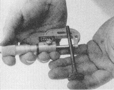
1. To install the recessed valve components on this type of head, you will need a small screwdriver, a valve spring clamp with a mandrel, a little white grease (cyatima) and lots of patience.
2. Lightly lubricate the valve stems and install them in their regular places in the cylinder head.
3. At the appropriate complete set establish where follows adjusting washers of valvate springs.
4. Install new oil seals (if provided by the design). If the cap sits on the guide sleeve, first lightly lubricate the outer surface of the latter. If an o-ring is used instead of a cap, it is installed after the valve spring has been compressed, but before the split lock crackers are seated on the valve stem.
5. Put the spring and its plate on the valve stem.
6. Install the mandrel and compress the spring with a special clamp.
7. Working with a screwdriver like a spatula, fill the bends of the split lock keys with grease, this will help to temporarily fix the keys on the valve stem before releasing the spring.
8. Prying with a screwdriver (reapply lube), put crackers in their regular places on the valve stem, pressing them tightly to the surface of the latter.
9. Slowly release the clamp compressing the valve spring - make sure that the crackers do not fall out - and remove it from the engine.
10. In the same manner, install the components on the remaining valves.
11. Install tappets, camshaft (s) (don't forget to check the valve clearances) and other components removed during dismantling.
Heads with lever-type pushers
1. Lightly lubricate the valve stems and install the latter in their regular places in the cylinder head.
2. At the appropriate complete set establish where follows adjusting washers of valvate springs.
3. Install new oil seals (if provided by the design). If the cap sits on the guide sleeve, first lightly lubricate the outer surface of the latter. If an o-ring is used instead of a cap, it is installed after the valve spring has been compressed, but before the split lock crackers are seated on the valve stem.
4. Put the spring and its plate on the valve stem.
5. Using the special tool, compress the valve spring.
6. Place crackers of the split lock on the valve stem.
7. Slowly release the valve spring - make sure that the crackers do not fall out of the groove on the valve stem.
8. Remove the spring compression tool from the head.
9. In the same manner, install the components on the remaining valves.
10. Install tappets, camshaft (s) (do not forget to adjust the valve clearances - see Chapter Settings and ongoing maintenance) and other components removed during dismantling.