
General information
During the reconditioning of the cylinder block, pistons with piston rings, main and connecting rod bearings of the crankshaft, timing drive components and the oil pump are usually replaced. On OHV engines, the camshaft and valve lifters must also be replaced.
If necessary, the cylinders are turned / the liners are replaced. Cylinder mirrors must be honed without fail.
The crankshaft is usually also subject to turning, followed by a selection of repair bearing shells.
Removal of stepped wear at the top of the cylinders
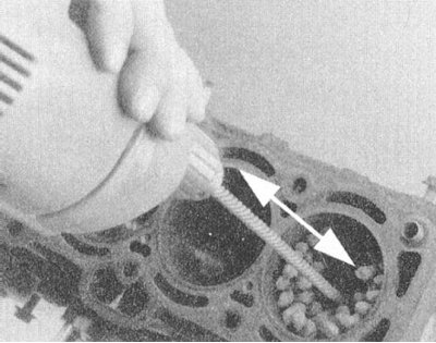
1. Due to the fact that during their working cycle the pistons do not reach the upper cut of the cylinder, at the end of their stroke a step is formed on the cylinder mirror, the presence of which prevents the removal of the connecting rod and piston assemblies and can cause damage to new pistons when they are installed in the engine.
2. There are several types of countersinks used to remove stepped wear on cylinders, all of them are relatively inexpensive tools.
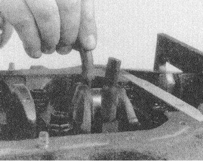
3. Rotate the crankshaft so that the piston of the corresponding cylinder drops to its lowest position.
4. Cover the bottom of the piston with a protective layer of rags
5. Ready a countersink and, following the tool manufacturers' instructions, machine the top of the cylinder to remove staggered wear.
Note. Try not to overdo it and not damage the cylinder mirror in its working part!
6. Remove the drill, rags and sawdust formed as a result of processing.
7. In a similar manner, remove the stepped wear from the mirrors of all cylinders.
Disassembly and cleaning
1. Mount the motor on a mounting stand or a sturdy workbench. Alternatively lay the unit on the garage floor on a couple of wooden blocks (transmission mating surface down). The position of the engine should provide free access to the fasteners of the caps of the lower heads of the connecting rods and the possibility of turning the crankshaft. All covers provided for by the design of the unit must be removed from the engine.
2. Remove the timing components and cylinder head from the engine. Remove the oil pan and oil intake assembly. If necessary, remove the oil pump drive, balancing and auxiliary shafts.
3. Remove staggered wear from the top of the cylinders (see above).
4. Turn over the engine so that direct access to a cranked shaft opened. Using a scriber or punch, mark the connecting rods in accordance with their belonging to their cylinders. Mark the main bearing caps in the same way.
5. Turn the engine over again, this time with the first cylinder up. Turn the crankshaft so that the piston of the first cylinder is at the bottom of its stroke. Loosen the fasteners and remove the cover of the lower head of the connecting rod of the first cylinder (make sure that the connecting rod bearing shell remains in the cap).
6. Pull the pieces of the fuel hose onto the mounting studs, thereby ensuring the protection of the neck of the shaft and the mirror of the cylinders from damage during the removal of the connecting rod assembly.
7. Using a wooden hammer handle, push the connecting rod up approximately 25 mm and remove the upper bearing shell from the bed in its lower head.
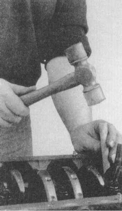
8. Continue to carefully tap the assembly up until the piston rings are released from the cylinder.
Attention! In the event of resistance, immediately stop tapping the assembly and make sure that the traces of stepped wear in the upper part of the cylinder mirror are completely removed!
9. Manually finally remove the connecting rod and piston assembly from the block. Insert the bearing shells in bed, reinstall the cap of the lower head of the connecting rod, slightly tightening the fasteners.
10. Acting in a similar manner, remove the remaining connecting rod and piston assemblies from the block.
Note. When servicing V-engines, the assemblies from one row of cylinders are first removed, then the engine is flipped up the second row and the remaining assemblies are removed.
12. At this point, the only component remaining in the block should be the crankshaft. Loosen the fasteners evenly and remove the main bearing caps in several steps (with inserts included).
13. Carefully remove the crankshaft from your beds in the block.
14. Thoroughly clean all removed components. If you are not going to assemble the engine immediately, place the block in a clean plastic bag.
Checking the Status of Components
1. When checking the condition of the engine block components, some special tools will be required. These tools include:
- Two or three micrometers for measuring the diameters of pistons and crankshaft journals;
- Dial gauge plunger type;
- Machine for evaluating the degree of deformation of connecting rods.
2. In the absence of the necessary tools at hand, checking the condition of the components should be entrusted to car service specialists.
3. Carefully inspect the block for cracks and other mechanical damage. Methods for detecting hidden defects are described in Section Restorative repair of the cylinder head, dedicated to checking the condition of the cylinder head. It would be most correct to entrust the inspection of the condition of the casting of the block to car service specialists.
Engine block
Checking the alignment of the main bearing beds
1. Check the beds of the main bearings in the block and covers for signs of overheating, scuffing and burrs and other mechanical damage. If necessary, give the block to the groove, or replace it. Light defects can be removed with a fine-toothed file.
2. Check the alignment of the bearing beds in the block using a flatness meter, laying the latter along the axis of the crankshaft gasket - if any play or gaps are detected, the block should also be machined. The caps of the main bearings must also be subjected to the corresponding boring to the repair size. After turning, the engine must be equipped with new liners of the appropriate repair size.
Checking the flatness of the mating surface of the block
1. The surface of the block mating with the cylinder head, also called the deck, must be thoroughly cleaned with the complete removal of all traces of the old gasket material, coal and tar deposits from it. The check is made using a flatness meter and a blade-type probe. First, the degree of nonflatness along the DP of the block is estimated, then along both of its diagonals.
2. If the amount of flatness exceeds 0.076 mm over a length of 15.2 mm (or 0.152 mm for the full length of the mating surface), the cylinder block is subject to turning.
Cylinders
1. Usually the working clearance of the pistons in the cylinders is 0.0381÷0.0635 mm.
2. Assess the external state of the cylinder mirrors and measure them. Measurements are made using a telescopic caliper and a micrometer in three sections and two mutually perpendicular planes. Analysis of the measurement results will determine the scope of the forthcoming restoration work. The ovality and taper of the cylinders must not exceed the allowable ranges. The measurements taken will allow in the future to determine the size of the clearances of the pistons in the cylinders.
3. The upper part of the cylinders is usually worn somewhat more than the lower part, which leads to the formation of a taper. If the taper value exceeds 0.305 mm, the cylinder must be turned.
4. In addition, usually the walls of the cylinders usually wear out more strongly on the thrust surfaces of the pistons, i.e. in a plane perpendicular to the axis of the crankshaft. This kind of wear leads to the formation of ovality of the cylinders, which should also not go beyond the permissible limits (see specs).
Crankshaft
1. Wash the crankshaft with solvent, then dry thoroughly using compressed air if possible. Don't forget to clean the oil holes with a stiff brush. Then wash them with solvent.
Attention! Wear protective goggles when using compressed air!
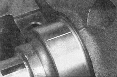
2. Check the crankshaft main and connecting rod journals for scoring, cavities, cracks, and signs of uneven wear. Inspect the entire surface of the shaft for cracks or other damage. To reveal hidden cracks, you should resort to magnetic particle flaw detection - give the shaft to a car service workshop.
3. Swipe the edge of a copper coin along the necks - if there are traces of copper on the surface, therefore, its roughness exceeds the allowable one and it is necessary to give the shaft to the groove.
4. Use a whetstone, file or scraper to remove burrs from the edges of the oil holes.
5. Check the remaining shaft surfaces for cracks and other mechanical damage. Hidden cracks are detected during a special inspection in a service station.
6. With a micrometer, measure the diameters of the main and connecting rod journals of the shaft. Measure the diameter of each neck at several points along the length and perimeter, which will allow you to evaluate the value of its taper and ovality, which should not go beyond the allowable ranges (see specs). The amount of crankshaft runout should also be assessed - a pair of V-blocks and a DTI meter will be required. If you do not have the necessary equipment, contact a car service specialist for help.
7. In the event that the wear / taper / ovality of the necks exceeds the permissible value, or mechanical damage to the surfaces occurs, the crankshaft should be turned into a groove. After turning the shaft, it is necessary to select new liners for the main and / or connecting rod bearings of the appropriate repair size.
8. Check up a condition of omental necks on both pins of a cranked shaft. The presence of developed grooves, burrs or scuffs will lead to the failure of new oil seals in the very near future. In some cases, the trunnions can be restored by turning and pressing special thin-walled bushings onto them. If this kind of repair is not possible, replace the shaft.
9. Check up a condition of loose leaves of radical and rod bearings.
Connecting rod and piston assemblies
1. Previously, the connecting rod and piston assemblies must be thoroughly cleaned. Piston rings must be removed.
Note. Piston rings must be replaced without fail.
2. Using a special tool, remove the rings from the pistons - try not to accidentally damage the walls of the latter.
3. Scrape off any carbon deposits from the piston crowns. After removing the main layer of deposits, sand the surface by hand with a wire brush or a piece of fine sandpaper.
Attention! Under no circumstances should wire attachments for an electric drill be used to clean pistons made of soft material and easily eroded!
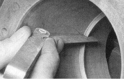
4. Using a special tool, clean the grooves for the installation of rings on the pistons. Alternatively, you can use a piece of an old piston ring for this purpose, but be careful not to scratch the bottom and walls of the groove and do not cut your fingers.
5. After removing the main deposits, wash the connecting rod assemblies with a solvent and dry them thoroughly, if possible using compressed air.
Attention! Remember to wear protective goggles when using compressed air! Check the patency of the oil return holes in the rear walls of the grooves for the installation of piston rings, as well as the oil holes in the lower heads of the connecting rods.
6. If the piston walls and cylinder bores are not damaged or excessively worn, and the engine block has not been machined or replaced, there is no need to replace the pistons either. Normal wear of the pistons is manifested in the form of vertical wear marks along the thrust surface and a slight slack in the fit of the upper compression ring in its groove. Do not forget that the replacement of piston rings is mandatory, regardless of their condition.
7. Carefully inspect each of the pistons for cracks in the skirt, around the protrusions for the installation of piston pins and in the area of \u200b\u200bthe rings.
8. Check the thrust surfaces of the piston skirt for scratches, the bottom for through holes and burnouts along the edge. The presence of scratches on the skirt can be regarded as a sign of prolonged overheating of the engine, or too early ignition of the air-fuel mixture - check the correct functioning of the cooling system. Burnouts along the edges of the bottom are evidence of detonation. In any case, the cause of the identified violation must be eliminated in order to avoid relapses. Intake air leaks, incorrect air-fuel mixture layout, incorrect ignition timing, incorrect functioning of ignition and EGR systems can also be possible reasons for the formation of the listed defects.
9. Pitting of pistons in the form of cavities indicates that coolant has entered the combustion chambers and / or crankcase of the engine. Again, make sure that the cause of the internal leaks is corrected.
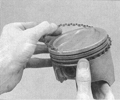
10. Assess the backlash of the piston rings in their grooves by inserting a new ring from the outside into your groove on the piston and using a blade-type feeler gauge to measure the remaining gap. Repeat the measurement at two or three points along the perimeter of the groove. Be careful not to mix up the compression rings (the top is different from the second). If the gap exceeds the allowable value (see specs), pistons must be replaced.
11. Determine the piston clearance in your cylinders, subtract from the cylinder diameters (see above) respective piston diameters. The piston diameter is measured along the thrust surface at an angle of 90°to the axis of the piston pin and at a given distance from the bottom. If the piston clearance in the cylinder exceeds the allowable value (see specs), the block should be given to the groove with a selection of new pistons and piston rings of a repair diameter.
12. Trying to rotate the components in opposite directions, evaluate the fit of the pistons on the connecting rods. The presence of any noticeable play indicates excessive wear on the joint. To correct the situation, the connecting rod and piston assemblies should be delivered to a car service workshop, where the necessary refurbishment and replacement of fingers will be carried out.
13. Performing the procedure for removing the pistons from the connecting rods (in case such a need arises) should also be entrusted to car service specialists. In parallel, connecting rods can be checked for signs of bending, twisting and other deformations using special diagnostic equipment.
Note. Unless necessary, pistons should not be removed from the connecting rods.
14. Check up rods on existence of cracks and other mechanical damages. Temporarily remove the lower head covers, remove the old bearing shells, wipe the beds in the covers and heads and check them for burrs, scuffs and roughness. When finished checking, put the liners in place, install the caps on the lower connecting rod heads, and finger-tighten the mounting bolts.
Note. If the engine is being repaired to eliminate finger knocking, replace the connecting rod assemblies.
Bearings
Status check
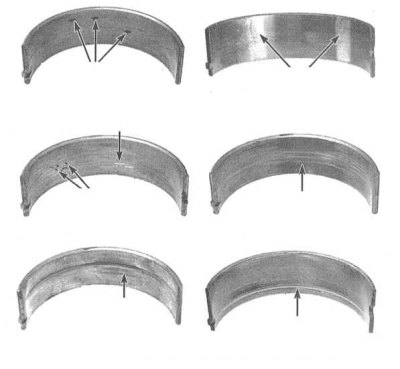
1. Despite the fact that the bearings of the crankshaft must be replaced during the overhaul of the engine, the old liners should be kept in order to carefully study their condition, the results of which can provide a lot of useful information about the general condition of the engine. The illustration shows examples of typical bearing shell defects.
2. Bearing failure can occur due to lack of lubrication, dirt particles, motor overload and corrosion. Regardless of the nature of the defects, the cause of the damage to the liners must be eliminated during the engine overhaul to avoid recurrence.
3. For inspection, remove the bearing shells from their beds in the engine block/connecting rod heads and main/connecting rod caps and lay them in installation order on a clean work surface. The organization of the placement of the liners will make it possible to link the nature of the identified defects to the state of the corresponding shaft journals.
4. Dirt and foreign particles enter the engine in various ways. They can be left inside the unit during assembly of the unit, or they can get through filters or the crankcase ventilation system. All particles that get into the engine oil eventually, sooner or later, end up in the bearings. Often, metal filings are embedded in the soft material of the liners, which are formed during the normal operation of the internal components of the engine. There is a high probability of the presence of traces of abrasive in the bearings, especially when due attention was not paid to cleaning the block after the completion of the engine reconditioning. Regardless of the way in which foreign particles enter the engine, they are highly likely to be embedded in the soft surface of the crankshaft bearing shells and are easily identified by visual inspection of the latter. Large particles usually do not linger in the liners, but leave noticeable marks in the form of scratches, cavities and scuffs on their surface and the surface of the shaft journals. The best guarantee against this kind of trouble is a responsible attitude to cleaning components after the completion of an engine overhaul and careful attention to cleanliness during assembly. Frequent, regular engine oil changes can also significantly extend bearing life.
5. Oil starvation can result from several different but often related phenomena. So, overheating of the engine leads to dilution of the engine oil and its displacement from the working clearances of the bearings. Lack of bearing lubrication can be attributed to excessive running clearances as well as normal leaks (internal or external). A common cause of oil being forced out of bearing clearances is constant over-revving of the engine. Violation of the patency of oil flows (usually associated with misalignment of holes when installing components) also leads to a reduction in the supply of lubricant to the bearings. A typical result of oil starvation is the complete or local wiping/pitting of the surface layer of liners from the metal substrate. In this case, the operating temperature can rise to such a level that the substrate acquires a bluish tint as a result of overheating.
6. The driving style of the car owner also has a significant impact on the service life of the bearings. Driving at low speed in high gear leads to significant overloads of the bearings, accompanied by the displacement of the oil film from their working gaps. This kind of overload leads to an increase in the plasticity of the liners and the appearance of cracks in the surface layer (fatigue strain). In this case, the surface material begins to crumble and separate from the steel substrate. Operation of the car in the urban cycle (frequent trips over short distances) leads to the development of bearing corrosion due to the fact that insufficient heating of the engine leads to condensation and the release of chemically aggressive gases. These products accumulate in engine oil, forming slags and acids. If such oil gets into the bearings, aggressive substances contribute to the development of corrosion of the liners.
7. Incorrect installation of liners during engine assembly can also cause their rapid destruction. Too tight fit does not provide the required working clearance of the bearings, which leads to their oil starvation. The result of getting under the liners (during their installation) foreign particles is the formation of elevations, the surface layer from which is quickly wiped off.
8. Balancing and auxiliary shafts can be equipped with annular bearings, the replacement of which should be entrusted to car service specialists.
Honing cylinder mirrors
1. Before assembling the engine, it is mandatory to honing the cylinder mirrors in order to achieve the correct fit of the piston rings on them, which ensures proper tightness of the combustion chambers.
Note. If you do not have the necessary tools at hand or do not want to do honing yourself, the work can be entrusted to the specialists of a car service workshop for quite a moderate fee.
2. Replace main bearing caps/bridge before honing (without inserts) and tighten the fixing bolts to the required torque.
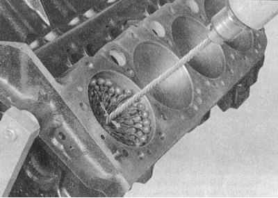
3. There are two types of hone for processing cylinder mirrors: hone type "bottle brush" and, more traditionally, a surface hone in the form of a nozzle with spring-loaded whetstones. Both tools provide the necessary quality of processing cylinder mirrors, although the use of the first one is preferable for an inexperienced mechanic. You will also need a sufficient amount of rags, special honing or just liquid machine oil, as well as an electric drill as a drive for honing nozzles. Proceed in the following order:
- a) Clamp the hone in the chuck of an electric drill, bring the spring-loaded whetstones / rods of the nozzle brush and thread the latter into the cylinder.
Attention! Don't forget to wear safety goggles or a face shield!
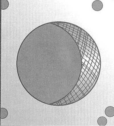
- b) Abundantly moisten the mirror of the treated cylinder with oil, turn on the drill and start reciprocating movements inside the cylinder with the nozzle. The speed of the vertical movement of the hone should ensure the application of a mesh pattern on the surface of the mirror of the cylinder with an angle of intersection of the sides of the mesh of about 60°. Spare no oil and try not to remove more material from the surface of the cylinder walls than is really necessary to achieve the desired result.
Note. Piston ring manufacturers may have their own requirements for the angle of intersection of the sides of the mesh pattern - carefully read the instructions on the package of the repair kit.
- c) Do not remove the hone from the cylinder before the drill stops completely! Continue to reciprocate the nozzle until it stops rotating. After stopping the drill, squeeze the whetstones and remove the hone from the cylinder. When using hone type "bottle brush" wait for the drill to stop completely, then remove the attachment while continuing to manually rotate the chuck in the normal direction.
- d) Wipe the cylinder mirror with a rag and proceed to honing the next one.
 |  |
4. Upon completion of processing, use a file to chamfer the upper edges of the cylinders - this processing is carried out in order to avoid difficulties with filling pistons with rings put on them into cylinders. Be extremely careful not to scratch the mirror of the cylinder with the needle file.
5. Finally, the entire unit should be thoroughly rinsed with a warm, soapy water solution.
Note. The cylinders can be considered washed when, after passing a white cloth moistened with oil on the mirror, there is no gray coating left on it. Be sure to clean all oil holes and channels with a cylindrical brush, then flush the block with a high-pressure water jet.
6. After washing, dry the block thoroughly and coat the machined surfaces with oil to protect them from corrosion. Wrap the block in a clean plastic bag before assembling the engine.
Assembly
1. First of all, it is necessary to prepare the workplace, paying special attention to the cleanliness of the surfaces and the availability of sufficient free space. Take care of equipping a place for storing the components to be installed. All parts to be installed must also be thoroughly cleaned and dried.
2. Fix the cylinder block to the mounting block and wash it thoroughly again with a solution of soapy water, paying special attention to cleaning the oil passages and water galleries. Dry the block, if possible with compressed air, then spray it with a WD-40® type anti-corrosion solution. Wipe the cylinder mirrors with a clean, lint-free cloth.
3. Reinstall the squeeze plugs and oil gallery plugs.
4. No less thoroughly clean the crankshaft and proceed to install it on the engine (see below).
Engine assembly procedure
1. Before proceeding with the assembly of the engine, make sure that you have all the necessary parts, materials and tools, which include the following:
- a) Standard set of locksmith tools;
- b) Torque wrench with 1/2-inch drive;
- c) Tool for putting on piston rings;
- d) Tool for crimping piston rings;
- e) Short lengths of fuel hose for fitting rod bearing caps onto studs;
- f) Measuring set Plastigage;
- g) A set of blade type probes;
- h) File with a small tooth;
- i) Fresh motor oil;
- j) Assembly motor or molybdenum-containing lubricant;
- k) gasket sealant;
- l) Sealant for fixing threaded connections.
2. To save time and minimize problems, assemble the engine in the following order:
- Four-cylinder engines
- a) Piston rings;
- b) crankshaft and main bearings;
- c) Connecting rod and piston assemblies;
- d) Rear crankshaft oil seal;
- e) Balancing assembly of the engine;
- f) Cylinder head with valve lifters;
- g) Camshafts;
- h) Balance shafts with sprockets;
- i) Gas distribution chain;
- j) Oil pump;
- k) Oil intake with strainer;
- l) Oil pan;
- m) Inlet pipeline and exhaust manifold;
- n) Cylinder head cover;
- o) Flywheel/Drive Disc.
- V6 engines
- a) Piston rings;
- b) crankshaft and main bearings;
- c) Connecting rod and piston assemblies;
- d) Rear crankshaft oil seal with holder;
- e) Oil pump;
- f) Oil pan;
- g) cylinder heads;
- h) Camshafts and valve lifters;
- i) Timing belt with gears;
- j) Timing drive covers;
- k) Cylinder head covers;
- l) Inlet pipeline and exhaust manifolds;
- m) Flywheel/Drive Disc.
Installation of piston rings
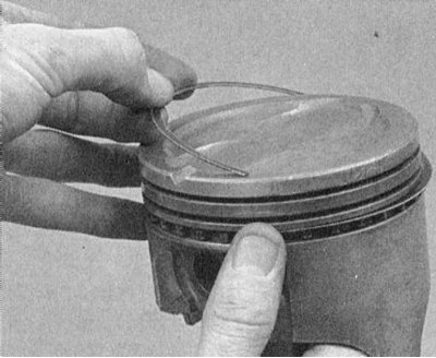
1. Before installing new piston rings, check the gaps in their locks. It is understood that the side clearances of the rings in the piston grooves have already been checked and comply with accepted standards (see above).
2. Lay out the connecting rod and piston assemblies with ring sets on the work surface of the workbench. From now on every set of rings will be tough "tied" to your piston. Now you can start measuring the gaps in the locks of the rings.
3. Fill the top (№ 1) compression ring inside the first cylinder of the engine and align it perpendicularly by pushing down the piston crown. The ring should be in the region of the lower limit of the working stroke of the rings in the cylinder.
4. Determine the gap in the lock of the ring with a blade-type feeler gauge Blade (I) the probe should slide tight in the lock. Compare the measurement result with the requirements of the Specifications. If the clearance is out of range either way, before taking any corrective action (see below), once again make sure that you do not mix up the rings.
5. If the gap is too small, it can be enlarged by boring with a fine toothed file (read the instructions for the kit beforehand - not all rings can be filed) Clamp the rectangular file in a vise, then lock the ring around the file so that the end of the latter is inside the circle. Slowly pull the ring towards you, removing excess metal from its ends in the lock. When you reach the end of the file, remove the ring, check the gap again, repeat the procedure if necessary.
Attention! In no case do not push the ring away from you onto the file, as this will cause the edges of the lock to converge, and there is a high risk of metal destruction.
6. Excessive clearance is not a crime if it does not exceed 0.51 mm. Once again, make sure that the purchased sets of rings meet the needs of your car engine in terms of their characteristics.
7. Repeat the procedure for the remaining rings (second compression and oil scraper) piston of the first cylinder, then for the rings of all other pistons. Remember that now each set of rings is uniquely "tied" to its piston, on which it should be installed.
8. Having checked and properly corrected the gaps in the locks of the rings, you can start putting them on your pistons.
9. The oil scraper is put on the piston first (bottom) ring. The oil scraper ring consists of three separate sections. First fill the spring expander into the lower groove of the piston. If the reamer is equipped with an anti-rotation tongue, make sure that the latter is in the counterdrill in the piston groove. Now install the lower working section of the ring into the groove. To avoid accidental damage to the working sections of the oil scraper ring, do not use any tool to install them - just insert one end of the section into the groove under / above the expander, press it firmly with your finger and, moving along the perimeter of the ring, fill the rest. Lastly, the upper working section of the ring is installed.
 |  |
10. Having seated all three components of the oil scraper ring in the lower groove of the piston, check the freedom of rotation (slip in the groove) upper and lower working sections.
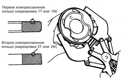
11. The next is the second (bottom) compression ring. The ring must be installed with the marking facing up (to the bottom of the piston).
Note. Strictly follow the instructions of the ring manufacturers, which are usually printed on the packaging of the kit. Do not confuse the second compression ring with the first (top) - they have different cross sections.
12. Using a special expander and making sure that the ring is turned with the marking up, put it in the middle groove on the piston. Try not to spread the ring lock more than is really necessary to smoothly put it on the piston.
13. Proceeding in a similar manner, install the first (upper) compression ring (marking up). Try not to confuse the top ring with the second one.
14. Alternately complete with rings all the remaining pistons.
Installing the crankshaft
1. Installation of the crankshaft is the first step in the actual assembly of the engine. It is understood that at this stage the engine block and the shaft itself have already been properly cleaned, checked and subjected to the necessary refurbishment.
2. Turn the engine upside down.
3. Give fixing bolts, remove covers of radical bearings/assembly of covers. Arrange the covers on the workbench in order of installation on the engine.
4. If you have not already done this, remove the old main bearing shells from your beds in the block and covers. Wipe the beds with a clean, lint-free cloth - they should be immaculately clean.
Checking the operating clearances of main bearings
Note. Avoid touching the new bearing surfaces with bare hands to avoid unwanted contact of the bearings with traces of oil and chemicals that are always present on the fingers.
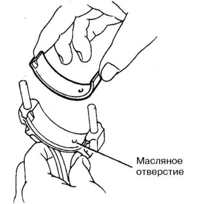
1. Wipe the backs of the new main bearing shells and place the oil grooved halves into their beds in the block. Insert the rest of the shell halves into the corresponding bearing caps. Make sure that the tongues of the liners enter the reciprocal landing grooves in the beds of the block and covers. The oil holes in the block must also be correctly aligned with the holes in the liners.
Attention! Under no circumstances should you attempt to hammer an unfitted liner into your bed with a hammer. Do not lubricate the bearings at this stage!
2. Wipe the surfaces of the bearings in the block and the crankshaft main journals with a clean, lint-free rag. Check the patency of the shaft oil holes, clean them if necessary. Any foreign particles contained in the oil paths will inevitably end up in the bearings.
3. Carefully wiped crankshaft carefully lay in the main bearings of the block.
4. Before finally installing the shaft, it is necessary to check the operating clearances in its main bearings.
5. Cut the calibrated plastic wire from the Plastigage measuring kit into lengths slightly shorter than the width of the bushings, and lay one piece of wire along each of the main shaft journals, parallel to their axis.
6. Wipe the surfaces of the liners in the covers and install the latter in their regular places. Try not to move the pieces of calibrated wire laid along the necks of the shaft. Lightly oil the threads of the mounting bolts and screw them in, fixing the covers.
7. In several stages, evenly tighten the cap screws to the required torque.
Attention! Do not allow the shaft to turn while tightening the fasteners!
8. Turn out bolts and carefully remove covers of radical bearings. Place the removed covers in the order in which they are placed on the engine. Take care not to damage the flattened gauge wire and do not turn the shaft. If any of the covers cannot be removed, gently tap it with a soft-faced hammer to loosen it.
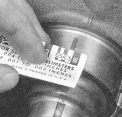
9. Using the width of the flattened threads, measured on the scale printed on the packaging of the Plastigage kit, determine the operating clearances of the bearings. Compare the measurement results with the requirements of the Specifications.
10. If the gap is out of tolerance, the wrong size bushings may have been installed. Before looking for new liners, make sure that no dirt or oil has fallen under the ones inserted at this stage. If the calibrated wire is flattened at one end more than at the other, this indicates the presence of a neck taper.
11. Carefully remove the gauge wire from the necks, scraping off all traces of it with some tool that is not too strong (like the edge of an old credit card). In extreme cases, you can use your own fingernail - the main thing is that there are no scratches or scratches on the surface of the necks / liners.
Final installation of the crankshaft
1. Carefully remove the crankshaft from the engine. Wipe the surfaces of the bearings in the block and evenly lubricate them with a thin layer of molybdenum or motor assembly grease. Don't forget to lubricate the thrust washers as well.
Attention! Try not to let grease get on the backs of the liners!
2. Make sure the crankshaft journals are absolutely clean, then lubricate (the same lubricant or clean engine oil) trunnion surfaces in contact with seals.
3. Install the rear shaft seal.
4. Wipe and lubricate the surfaces of the liners in the block, then lay the shaft in its regular place. Establish a cover of the back bearing, then all others, except persistent. Tighten the cover fasteners to the required torque.
5. Install the thrust bearing cover, screw in the bolts of its fastening and tighten them by hand.
6. Slide the shaft forward against the thrust surface of the upper bearing shell. While holding the shaft still, press the thrust bearing cap back to align the thrust surfaces of both bushings.
7. Pressing the shaft forward, tighten the cover fastening bolts with the required force.
8. To measure the axial play of the crankshaft, fix the dial gauge on the block by pressing its plunger against the end surface of the front shaft pin.
9. Carefully press the shaft back until it stops and, holding it in the depressed position, zero the meter.
10. Move the shaft forward to the end of its stroke and read the gauge.
11. If the measurement result is out of range (see specs), replace the thrust bearing shells and recheck. If necessary, give the shaft for inspection to a car service workshop.
Installing connecting rod and piston assemblies and checking the working clearances in the connecting rod bearings of the crankshaft
Preparation
1. Before installing the connecting rod and piston assemblies, the cylinder walls must be thoroughly wiped, traces of stepped wear are completely removed from their upper edges and a chamfer is removed. It is understood that the crankshaft is already installed in its regular place in the block.
2. Remove the cover of the lower head of the connecting rod assembly of the first cylinder (make sure that there are factory marks or marks applied during the dismantling process). Remove the old bearing shells from the connecting rod head and its cover and carefully wipe their beds with a clean, lint-free rag.
Checking the operating clearance of the connecting rod bearing
Note. Avoid touching the new bearing surfaces with bare hands to avoid unwanted contact of the bearings with traces of oil and chemicals that are always present on the fingers.
1. Wipe the back of the new top bearing and place it in the bearing bed in the connecting rod head. Make sure the oil holes are aligned and that the guide tab of the bushing is in the reciprocal groove in the connecting rod. In no case do not tap the liner into the bed with a hammer. Do not lubricate the bearing with anything at this stage.
2. Wipe the back of the second bearing and place it in the connecting rod cap. Again, make sure that the tongue falls into the reciprocal groove. Do not use any lubricant - it is extremely important that the mating surfaces of the bearing and connecting rod remain absolutely clean and dry.
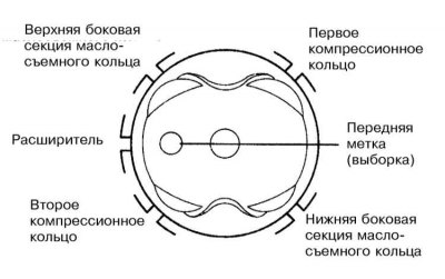
3. Arrange piston rings locks as it is shown in an illustration.
3. Place fuel hose pieces on the bearing cap bolts.
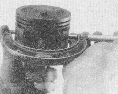
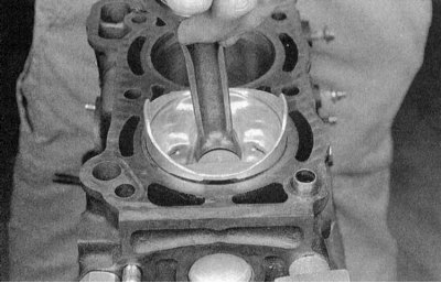
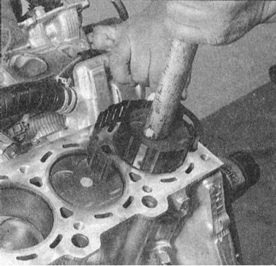
4. Lubricate the piston and piston rings with clean engine oil. Slide the mandrel of the ring crimping tool onto the piston. Leave the piston skirt protruding from the tool mandrel by about 6 mm for easy filling into the cylinder. The rings must be pressed flush with the forming surface of the piston.
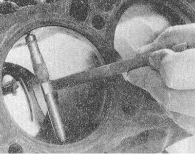
5. Rotate the crankshaft so that the neck of the first crank is in the BDC position. Lubricate the mirror of the first cylinder with impellent oil.
6. Turning the assembly with the markings on the bottom of the piston forward along the engine, carefully fill the connecting rod into the first cylinder of the block. Insert the piston skirt into the cylinder, firmly pressing the lower edge of the mandrel of the ring crimping tool against the surface of the block.
7. Tap the top edge of the mandrel to ensure that it is firmly pressed against the block around the entire perimeter of the bottom edge.
8. Gently tapping on the bottom with a wooden handle of a hammer, insert the piston into the cylinder, while directing the lower head of the connecting rod to the neck of the corresponding crankshaft crank. Piston rings can suddenly pop out from under the tool mandrel, so constantly monitor the tightness of pressing against its block. Act slowly, if the slightest resistance occurs, immediately stop the piston knocking. Find out the cause of jamming and eliminate it.
Attention! Never try to push the piston into the cylinder by force - this can lead to mechanical damage or destruction of the piston rings!
9. After the introduction of the connecting rod and piston assembly into the engine, before the final installation of the cover of the lower head of the connecting rod, you should check the working clearance of the connecting rod bearing of the crankshaft.
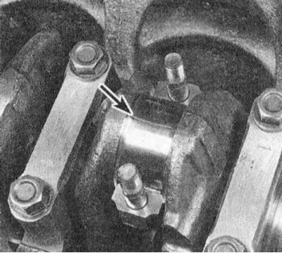
10. Cut a piece of calibrated plastic wire from the Plastigage measuring set, slightly shorter than the width of the connecting rod bearing shell, and lay it along the first crankshaft journal, parallel to the axis of the latter.
11. Wipe the bearing surface in the connecting rod cap and install the cap on the connecting rod. Make sure that the mark on the cover is turned in the same direction as the mark on the connecting rod.
12. Lightly lubricate the bottom ends of the heads of the fixing bolts with clean engine oil, screw in the bolts and tighten them in three stages with the required force.
Note. Use a thin-walled socket to avoid jamming the key. If there are signs of a wrench jamming between the nut and the connecting rod, slightly raise the head and continue tightening. Do not allow the crankshaft to rotate during the entire procedure.
13. Give fixture and carefully remove a cover from a rod. Take care not to damage the flattened piece of gauge wire.
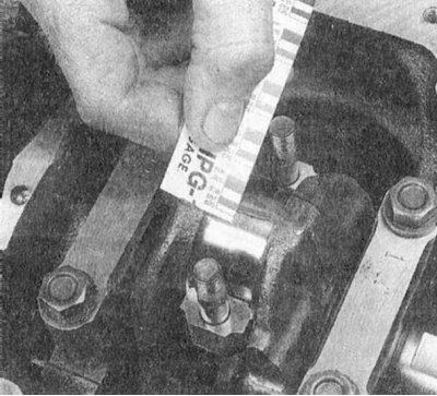
14. Using the flattened wire width, measured on the scale printed on the Plastigage package, determine the operating clearance in the bearing. Compare the measurement result with the requirements of the Specifications.
15. If the clearance is out of range, before looking for liners of a different size, check if dirt / oil has got under the backs of the liners nested in the connecting rod and the cover of the liners. Re-measure the diameter of the shaft journal. The flattening of the wire from one end more than from the other indicates the presence of a neck taper.
Final installation of the connecting rod and piston assembly
16. Using your fingernail or the edge of an old credit card, carefully scrape off all traces of gauge wire from the journal and/or bearing surface.
17. Make sure that both bearing surfaces are absolutely clean, then evenly lubricate them with a thin layer of molybdenum or motor assembly grease. To gain access to the surface of the upper bearing, you will have to push the piston into the cylinder a little - do not forget to put protective hoses on the connecting rod cap bolts to avoid damaging the surface of the shaft journal. Try to prevent the piston rings from popping out of the cylinder.
18. Return the connecting rod to its place, carefully putting it with the lower head on the neck of your crank, remove the protective hoses from the bolts, install the cover, and in three stages tighten the fixing nuts to the required force.
Note. Track the correct alignment of the marks on the connecting rod cap and its lower head.
19. Repeat the entire procedure for the remaining connecting rod and piston assemblies.
20. Keep the following important points in mind:
- a) Make sure that dirt does not get on the backs of the liners and their beds in the connecting rods and covers;
- b) Make sure that each assembly is installed exactly in its cylinder (even in the case of new components, as the piston ring gaps have been adapted to specific cylinders);
- c) Pistons must be marked on their bottom forward of the engine (towards the timing drive);
- d) Do not forget to lubricate the cylinder mirrors with engine oil before installing the assemblies;
- e) Do not forget to lubricate the bearings before final installation of the covers (after checking the working clearances in the last).
21. Having finished installing the connecting rod and piston assemblies, check the freedom of rotation of the crankshaft by turning it several times by hand.
22. In conclusion, it is necessary to check the axial play of the crankshaft again (see above).
23. Compare the results of the end play measurement with the requirements of the Specifications. If the backlash was normal before disassembling the engine and old connecting rod and piston assemblies were used, there should be no surprises. If the backlash goes beyond the permissible limits after replacing the connecting rods, the latter must be removed from the engine and sent to a car service workshop for appropriate machining.