
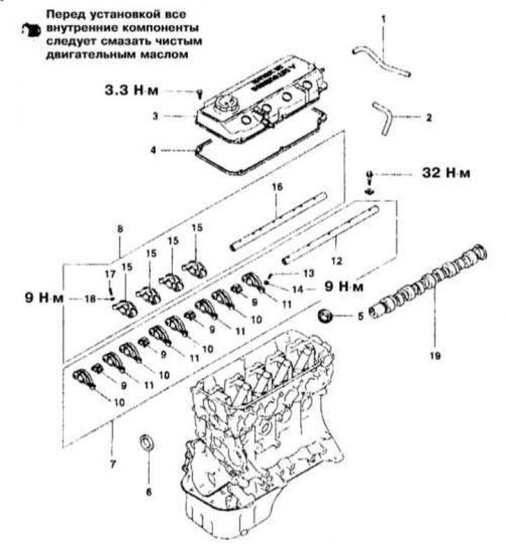
Valve Drive Component Installation Details on 1.5L Models
1 - Breather pipe; 2 - PCV hose; 3 - Cylinder head cover; 4 - Sealing gasket; 5 - Oil seal; 6 - Rocker arms of the valve drive with an axis; 7 - Rocker arms of the valve drive with an axis; 8 - Rocker arms D; 9 - Wavy washers; 10 - Remote bushings; 11 - Rocker C; 12 - Axis of the rocker arms of the exhaust valve drive; 13 - Rocker B; 14 - Rocker springs; 15 - Rocker A; 16 - Axis of the rocker arms of the intake valve drive; 17 - Adjusting screw; 18 - Nut; 19 - Camshaft
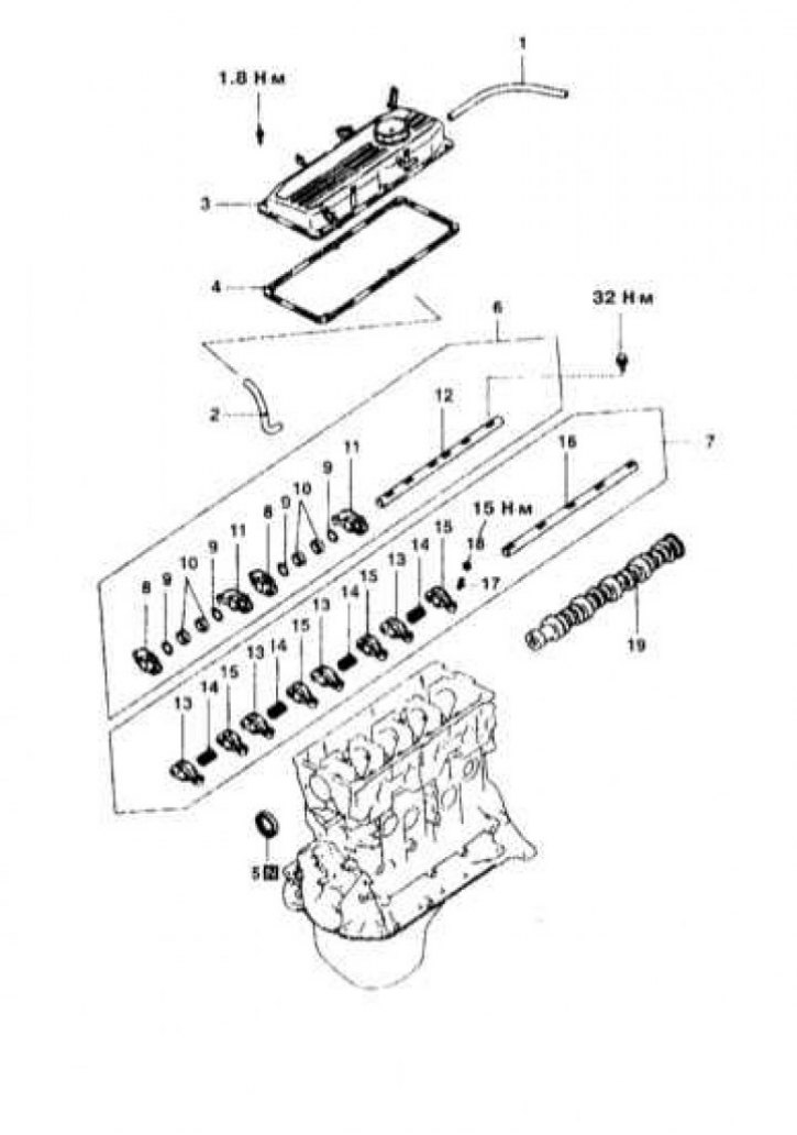
Valve Drive Component Installation Details on 1.8L Models
1 - Breather pipe; 2 - PCV hose; 3 - Cylinder head cover; 4 - Sealing gasket; 5 - Oil seal; 6 - Oil seal; 7 - Rocker arms of the valve drive with an axis; 8 - Rocker arms of the valve drive with an axis; 9 - Springs of the axes of the rocker arms; 10 - Rocker A; 11 - Rocker B; 12 - Axis of the rocker arms of the intake valve drive; 13 - Adjusting screw; 14 - Nut; 15 - Rocker C; 16 - Axis of the rocker arms of the exhaust valve drive; 17 - Adjusting screw; 18 - Nut; 19 - Camshaft
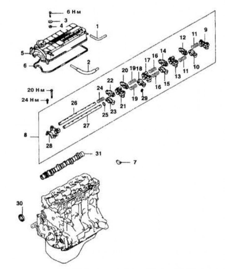
Valve Drive Component Installation Details on 2.0L Models (SOHC)
1 - Breather pipe; 2 - PCV hose; 3 - Sealing washer; 4 - Oil seal; 5 - Cylinder head cover; 6 - Sealing gasket; 7 - Semicircular seal; 8 - Rocker arms of the valve drive with axes; 9 - Rear bearing cover; 10 - Rocker arm D; 11 - Springs; 12 - Rocker arm D; 13 - Bearing cover No. 4; 14 - Rocker C; 15 - Rocker C; 16 - Springs; 17 - Bearing cap No. 3; 18 - Rocker D; 19 - Springs; 20 - Rocker D; 21 - Bearing cap No. 2; 22 - Rocker C; 23 - Rocker C; 24 - Spring; 25 - Wavy washer; 26 - The right axis of the rocker arms; 27 - Left axis of rocker arms; 28 - Front bearing cap; 29 - Valve clearance corrector; 30 - Oil seal; 31 - Camshaft
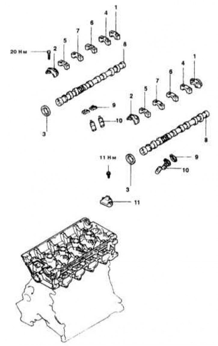
Valve Drive Component Installation Details on Models Equipped with 1.6L and 2.0L DOHC Engines
1 - Rear bearing cover; 2 - Front bearing cover; 3 - Camshaft seal; 4 - Bearing cover No. 5; 5 - Bearing cover No. 2; 6 - Bearing cover No. 4; 7 - Bearing cover No. 3; 8 - Camshaft; 9 - Valve rocker arms; 10 - Valve clearance hydraulic corrector; 11 - Oil dispenser housing
Valve Drive Component Installation Details on Models Equipped with 2.4L Engines
1 - Gas cable; 2 - Breather pipe; 3 - PCV hose; 4 - Candle wires; 5 - Cylinder head cover; 6 - Ignition distributor; 7 - Gas distribution belt; 8 - Camshaft gear; 9 - Camshaft seal; 10 - Assembling the rocker arms of the intake valve drive with its axis; 11 - Assembling the rocker arms of the exhaust valve drive with its axis; 12 - Camshaft
Valve Actuator Component Installation Details on Models Equipped with 3.0L DOHC Engines
1 - Transition nozzle for connecting the crankshaft position sensor (CKP) (models until 1992 issue.); 2 - Circular seal (models since 1993 issue.); 3 - Camshaft seal; 4 - Front bearing cover; 5 - Rear bearing cover; 6 - Bearing cover No. 2; 7 - Bearing cover No. 4; 8 - Bearing cover No. 3; 9 - Camshaft; 10 - Valve drive rocker; 11 - Hydraulic valve clearance corrector
Valve Drive Component Installation Details on Models Equipped with 3.0L SOHC Engines
1 - Cylinder head cover; 2 - Sealing gasket; 3 - Ring sealing insert; 4 - Support bracket "A" discharge chamber of the inlet pipeline; 5 - Camshaft oil seal; 6 - Adapter nozzle of the ignition distributor; 7 - O-ring; 8 - Assembling the valve drive; 9 - Bearing cover No. 4; 10 - Rocker arms of the valve drive; 11 - Springs; 12 - Bearing cap No. 3; 13 - Bearing cap No. 2; 14 - Axis of rocker arms "IN"; 15 - Rocker axle "A"; 16 - Bearing cap No. 1; 17 - Valve clearance regulator; 18 - Camshaft
Valve Drive Component Installation Details on Models Equipped with 3.5L Engines
1 - Cylinder head cover; 2 - Sealing gasket; 3 - Sealing cuff; 4 - Camshaft seal; 5 - Assembling the valve drive mechanism; 6 - Assembling the valve drive mechanism; 7 - Springs of the axis of the rocker arms; 8 - Rocker A; 9 - Rocker B; 10 - Axis of rocker arms; 11 - Valve clearance regulator; 12 - Rocker C; 13 - Axis of rocker arms; 14 - Valve clearance regulator; 15 - Thrust cover; 16 - O-ring; 17 - Camshaft; N - Replace
Engines 1.5 l
Removing
1. The installation details of the components of the valve drive mechanism on 1.5L engines are shown in the illustration.
2. Disconnect the negative cable from the battery.
If the stereo system installed in the car is equipped with a security code, before disconnecting the battery, make sure that you have the correct combination to activate the audio system!
3. Bring the engine to the TDC position of the end of the compression stroke of the piston of the first cylinder.
4. Disconnect the throttle cable, breather tube and PCV hose.
5. Mark position of the case of the distributor of ignition concerning the block of the engine and remove the distributor.
6. Remove the cylinder head cover and its sealing gasket.
7. In several steps, evenly loosen the fixing bolts and remove the rocker axles from the cylinder head.
8. Remove timing covers.
9. Remove the timing belt assembly.
Try to prevent the camshaft and shafts from turning when the timing belt is removed!
10. Holding the camshaft gear from turning, unscrew the bolt of its fastening.
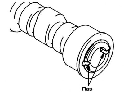
11. Remove the camshaft gear - note that the shaft must be turned with the hole for the guide pin up.
12. Remove the camshaft oil seal from the front wall of the cylinder head.
13. Remove the camshaft.
14. Carefully inspect all removed components for signs of excessive wear and damage.
Installation
1. Lubricate the camshaft with thick machine oil and lower it into its seat in the cylinder head - make sure that the shaft is turned with a hole for the guide pin for 12 hours.
2. Measure the axial play of the camshaft against the thrust casing. If the measurement result is out of range (0.05÷0.20 mm), replace the camshaft thrust bearing.
3. Install a new oil seal, - before installing the oil seal lips should be lubricated with clean engine oil.
4. Place the gear wheel on the camshaft pin. Screw the mounting bot and, holding the shaft from turning, tighten it with the required force (70 Nm).
5. Install the timing belt.
6. Install timing covers.
7. Install rocker arm assemblies with your axles. Tighten the mounting bolts evenly in several stages to the required torque (32 Nm).
8. Check up adjustment of valvate backlashes, pick up a sealing lining and establish a cover of a head of cylinders. Screw in the mounting bolts and tighten them to the required torque (1.8 Nm).
9. Having followed the alignment of the landing marks applied during the dismantling, install the ignition distributor on the engine.
10. Restore the original connection of the throttle cable, breather tube and PCV hose.
11. Connect a negative wire to the battery and check up correctness of installation of an advancing angle of ignition. Make appropriate adjustments if necessary.
Engines 1.8 l
Removing
1. Details of installation of components of the mechanism of a drive of valves on engines of 1.8 l are presented on an accompanying illustration.
2. Disconnect the negative cable from the battery.
If the stereo system installed in the car is equipped with a security code, before disconnecting the battery, make sure that you have the correct combination to activate the audio system!
3. Bring the engine to the TDC position of the end of the compression stroke of the piston of the first cylinder.
4. Mark and disconnect spark plug wires.
5. Mark position of the case of the distributor of ignition concerning the block of the engine. Remove the distributor.
6. Disconnect the wiring harness from the air flow measurement sensor and remove the air cleaner cover.
7. Disconnect the throttle cable, breather tube and PCV hose.
8. Remove the cylinder head cover and its gasket.
9. In several stages, evenly loosen the fixing bolts and remove the rocker axles from the cylinder head.
10. Remove timing covers.
11. Remove the timing belt assembly.
Try to prevent the camshaft and shafts from turning when the timing belt is removed!
12. Holding the camshaft gear from turning, unscrew the bolt of its fastening.
13. Remove the camshaft gear - note that the shaft must be turned with the hole for the guide pin up.
14. Remove the camshaft oil seal from the front wall of the cylinder head.
15. Remove the camshaft.
16. Carefully inspect all removed components for signs of excessive wear and damage.
Installation
1. Lubricate the camshaft with clean engine oil and lower it into its seat in the cylinder head - make sure that the shaft is turned with a hole for the guide pin for 12 hours.
2. Measure the axial play of the camshaft against the thrust casing. If the measurement result is out of range (0.05÷0.20 mm), replace the camshaft thrust bearing.
3. Install a new oil seal, - before installing the oil seal lips should be lubricated with clean engine oil.
4. Place the gear wheel on the camshaft pin. Screw the mounting bot and, holding the shaft from turning, tighten it with the required force (90 Nm).
5. Install the timing belt.
6. Install timing covers.
7. Install rocker arm assemblies with your axles. Tighten the mounting bolts evenly in several stages to the required torque (32 Nm).
8. Check up adjustment of valvate backlashes, pick up a sealing lining and establish a cover of a head of cylinders. Screw in the mounting bolts and tighten them to the required torque (3.3 Nm).
9. Having followed the alignment of the landing marks applied during the dismantling, install the ignition distributor on the engine.
10. In accordance with the markings made during the dismantling process, connect the spark plug wires.
11. Restore the original connection of the throttle cable, breather tube and PCV hose.
12. Connect the wiring harness to the air flow measurement sensor and replace the air cleaner cover.
13. Connect the negative cable to the battery.
14. Start the engine and warm it up to normal operating temperature.
15. Check up correctness of installation of turns of idling and a corner of an advancing of ignition. Make appropriate adjustments if necessary.
2.0L SOHC engines
Removing
1. Details of installation of components of the valve drive mechanism on 2.0L SOHC engines are shown in the illustration.
2. Disconnect the negative cable from the battery.
If the stereo system installed in the car is equipped with a security code, before disconnecting the battery, make sure that you have the correct combination to activate the audio system!
3. Disconnect the breather tube and PCV hoses.
4. Remove the support bracket and take the throttle cable to the side.
5. Install the valve clearance adjusters on the rocker arms (tools MD998443).
6. Remove the cylinder head cover and semicircular seals.
7. Mark position of the case of the distributor of ignition concerning a head of cylinders. Remove the distributor.
8. Remove timing covers and timing belt (see Section Removing and installing timing cover and timing belt).
9. Remove the camshaft gear.
10. Turn out fixing bolts and remove from the engine an axis of yokes with yokes and covers of bearings.
11. Remove the camshaft from the cylinder head. Assess the condition of the bearing journals of the shaft.
12. Measure the height of the camshaft lobes. Compare the measurement results with the requirements of the Specifications.
13. Assess the condition of the bearing surfaces in the cylinder head.
14. Replace any excessively worn or damaged components.
Installation
1. Lubricate the camshaft with clean engine oil and lower it into its seat in the cylinder head.
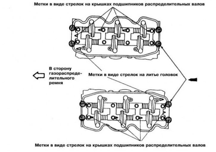
2. Install the bearing caps each in its place. Follow the correct orientation of the marks in the form of arrows applied to the roofs.
3. Install the rocker arm assembly with axles into the head. Working from the center outward, evenly tighten the bearing cap bolts in three steps to the required torque (20 Nm).
4. Using a suitable mandrel, fit the camshaft oil seal into the head, - before installing the oil seal lips, lubricate with clean engine oil.
5. Install the camshaft gear. Screw in the fixing bolt and tighten it to the required torque (90 Nm).
6. Install the timing belt.
7. Having followed the correct alignment of the landing marks applied during the dismantling process, reinstall the ignition distributor.
8. Remove the valve adjuster fixation tools.
9. Establish a cover of a head of cylinders and other components removed for the purpose of providing access.
10. Connect the negative cable to the battery. Start the engine and check it for signs of leaks.
11. Check up installation of a corner of an advancing of ignition. Make appropriate adjustments if necessary.
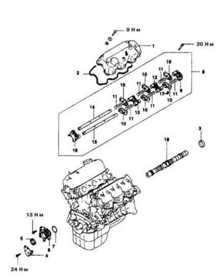
1.6L and 2.0L DOHC engines
Removing
1. Installation details of the valve actuator components on the 1.6L and 2.0L DOHC models are shown in the illustration.
2. Disconnect the negative cable from the battery.
If the stereo system installed in the car is equipped with a security code, before disconnecting the battery, make sure that you have the correct combination to activate the audio system!
3. Remove the support bracket and move the throttle cable aside.
4. Remove the breather tube and disconnect the PCV hose.
5. Mark and disconnect spark plug wires.
6. Mark position of the case of the distributor of ignition concerning a head of cylinders. Remove the distributor.
7. Remove the cylinder head cover.
8. Using tools type MD9984433, fix the valve lifters.
9. Remove timing covers and timing belt (see Section Removing and installing timing cover and timing belt).
10. Holding the camshaft from turning with a wrench, unscrew the fixing bolt and remove the timing gear.
11. Remove the valve drive assembly from the cylinder head.
12. Remove the camshafts from the head. Assess the condition of the bearing journals of the shafts.
13. Estimate a condition and bearing surfaces in a head of cylinders and covers of bearings of camshafts.
Installation
1. Lubricate the camshafts with clean engine oil and lower them into their seats in the cylinder head. The procedure for tightening the fasteners of the camshaft bearing caps is shown in the illustration.
2. Install valve train components (rockers). Tighten the fixing bolts to the required torque (29÷35 Nm).
3. Having previously lubricated with clean engine oil, install the camshaft oil seals - use a socket head of the appropriate size, or a piece of pipe of a suitable diameter, as an edit to fit the oil seals.
4. Install the camshaft gear. Screw in the fixing bolt and tighten it to the required torque (90 Nm).
5. Install the timing belt and front timing covers.
6. Having followed the correct alignment of the landing marks applied during the dismantling process, put the ignition distributor in place.
7. Remove the fixtures fixing the valve clearance adjusters.
8. After replacing the gasket, reinstall the cylinder head cover.
9. Connect the BB wires to the spark plugs (each to his own - follow the markings).
10. Connect breather tube and PCV hose.
11. Connect the negative cable to the battery.
12. Start the engine, warm it up to normal operating temperature and check the idle speed and ignition timing settings. Make appropriate adjustments if necessary.
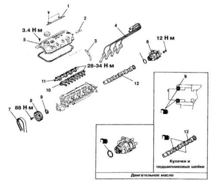
Engines 2.4 l
Removing
1. Details of installation of components of the mechanism of a drive of valves on models 2.4 l are provided on an accompanying illustration.
2. Disconnect the negative cable from the battery.
If the stereo system installed in the car is equipped with a security code, before disconnecting the battery, make sure that you have the correct combination to activate the audio system!
3. Disconnect the throttle cable, breather tube and PCV hoses.
4. Disconnect the spark plug wires and remove the cylinder head cover.
5. Turning the crankshaft clockwise, achieve the alignment of the TDC alignment marks (the camshaft gear should turn with the mark to the level of the mating surface of the cylinder head and the guide pin for 12 hours (up).
6. Remove timing covers.
7. Remove the timing belt (see Section Removing and installing timing cover and timing belt).
8. Using a wrench to be put on the flats located between the bearing journals No. 2 and 3, block the camshaft from turning and unscrew the bolt of its gear wheel. Remove the gear.
9. Loosen the mounting bolts in two or three steps, mark and remove the camshaft bearing caps.
If the caps cannot be removed, gently tap the rear end of the camshaft with a soft-faced hammer.
10. Remove the camshafts from the cylinder head.
11. Remove the rocker arms of the valve drive and hydraulic valve clearance adjusters, - fold all the components of the valve drive in an organized manner, since during assembly they must be installed strictly in their original places.
Installation
1. Install hydraulic valve clearance adjusters and rocker arms in the valve head.
2. Lubricate the camshafts with thick engine oil and lower them into their seats in the cylinder head.
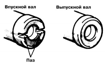
The intake shaft can be easily distinguished from the exhaust shaft by the presence of a groove in the end surface of the rear trunnion - the groove serves to drive the rotation angle sensor.
3. Assess the condition of the bearing journals and shaft cams. Check the oil passages in the cylinder head. Visually assess the condition of the rocker rollers, check the freedom of their rotation. Replace defective or worn components.
Rocker arms and hydraulic valve correctors should be replaced as a complete set.
4. Make sure that the camshafts are turned with the guide pins inserted into the end surfaces of the front pins upwards.
5. Install bearing caps. In two or three stages, evenly tighten the fixing bolts of the covers with the required force (20 N·m).
Bearing caps Nos. 2 and 5 have the same shape. On the cover of the first bearing, only lettering is provided (L - for intake shaft or R - for exhaust). On other covers, the marking is double, showing, in addition to belonging to its shaft, also the number of the cover. Follow the correct fit of the rocker arms on the hydraulic corrector assemblies and the ends of the valve stems.
6. Having previously lubricated with clean engine oil, install the camshaft seals - use a socket head of the appropriate size, or a piece of pipe of a suitable diameter, as an edit to fit the seals.
7. Install the camshaft gears. Screw in the mounting bolts and tighten them with the required force (80÷100 N·m).
In the process of tightening the bolt, keep the shaft from turning with a wrench by the flats provided between the journals of the 2nd and 3rd bearings.
8. Install the timing belt and front timing covers.
9. After replacing the gasket, install the cylinder head cover.
10. Reinstall other components removed for access.
11. Connect the negative cable to the battery.
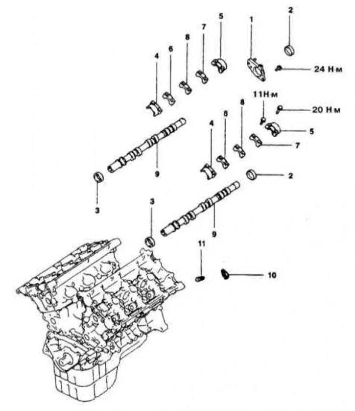
3.0L DOHC engines
Removing
1. Details of the installation of the components of the valve actuator on the models 3.0L DOHC are shown in the illustration.
2. Relieve pressure in the supply system (see chapter Power and exhaust systems).
3. Disconnect the negative cable from the battery.
If the stereo system installed in the car is equipped with a security code, before disconnecting the battery, make sure that you have the correct combination to activate the audio system!
4. Remove the air path pressure chamber.
5. Remove the front covers and timing belt.
6. Remove center cap, breather tube, PCV hoses and spark plug wires.
7. Remove the cylinder head cover (do not forget to remove the semi-circular seal).
8. Having marked the installation position, remove the CKP sensor from the rear camshaft stub.
9. With the appropriate vehicle equipment, remove the camshaft position sensor from the front wall of the engine (CMP).
10. Holding the camshafts from turning with a wrench for the specially provided flats, unscrew the fixing bolts and remove the gear wheels. Try to remember the installation position of the knock sensor pin.
11. Loosen the camshaft bearing cap bolts in two or three steps.
12. Having previously marked, remove the bearing caps, - if necessary, gently tap on the rear end of the shaft to release the caps.
13. Mark and remove both camshafts from the cylinder head.
14. Remove the valve drive components - try to remember the exact installation position of each part.
15. Assess the condition of the bearing journals and camshaft cams, as well as the working surfaces in the head beds and bearing caps.
Installation
Before installation, the valve train components should be lubricated with clean engine oil.
1. Remove the air from the hydraulic correctors and install the assemblies of the latter each in their seat in the cylinder head.
2. Install the valve drive assembly into the head.
3. Lubricate the camshafts with clean engine oil and install them in the cylinder head.
On Diamante models, the camshafts are easily distinguished from each other by a special letter marking applied to the flats of the hex section. The intake shaft is usually marked with the letters B or J, the exhaust shaft is D or K, respectively. Make sure the anti-knock pins are installed correctly to avoid damage to the valves due to contact with the piston crowns.
4. In accordance with the identification marking, install the camshaft bearing caps in their original places.
The letter I in the marking on the cover indicates the intake camshaft, E - exhaust, the number corresponds to the bearing number. Tighten the cover bolts evenly in two or three steps to the required torque (11 Nm - for bearing cap bolts No. 2, 3 and 4 and 20 Nm - for front and rear cap bolts). Make sure that the front marks on the 2nd, 3rd and 4th bearing caps are correctly aligned with the mating marks on the cylinder head.
5. Lubricate with clean engine oil and install the front camshaft oil seals.
6. Holding the shafts from turning by the specially provided flats with a wrench, install the timing gears on their trunnions, screw in the fixing bolts and tighten them with the required force (90 Nm).
7. If removed, reinstall the camshaft position sensor. Screw in the mounting bolts and tighten them with the required force (9 Nm).
8. Achieving the correct combination of landing marks, fix the CKP sensor on the rear side of the camshaft. Tighten the sensor mounting nut to 12 Nm.
9. Get the alignment marks of the timing gears aligned and install the timing belt on the engine.
10. Install the cylinder head cover and semicircular sealing insert.
11. Install the intake manifold pressure chamber assembly.
12. Connect the BB wires to the spark plugs. Install the center cap and restore the original breather tube and PCV hose connection.
13. Connect the negative cable to the battery. Start the engine and check it for signs of leaks.
3.0L SOHC engines
Removing
1. Details for installing the valve train components on 3.0L SOHC models are shown in the illustration.
2. Disconnect the negative cable from the battery.
If the stereo system installed in the car is equipped with a security code, before disconnecting the battery, make sure that you have the correct combination to activate the audio system!
3. Bring the engine to the TDC position of the end of the compression stroke of the piston of the first cylinder.
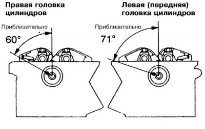
4. When removing the right (front) camshaft, mark the position of the slider and distributor housing and remove the assembly of the latter from the engine block.
5. Remove the intake manifold pressure chamber support bracket.
6. Remove the adapter adapter of the ignition distributor and its sealing ring.
7. Using special tools MB9g67 and MD998719, loosen the camshaft sprocket mounting bolt.
8. Turn out the fixing bot and remove the camshaft gear - try to remember the position of the anti-knock finger (guide pin).
9. Using special tools MD998443, fix the valve clearance hydraulic correctors on the rocker arms of the valve drive.
10. Release bolts of fastening of covers of bearings of a camshaft.
11. Remove the components of the valve drive mechanism - try to remember the installation position of the rocker arms and their axes. Remove the bearing caps of the camshaft to be removed.
12. Remove the camshaft from the cylinder head and evaluate the condition of its cams and bearing journals.
Installation
1. Lubricate the camshaft (s) thick engine oil and lower it into place in the cylinder head.
The camshaft of the right cylinder head is easily distinguished by the presence of a groove in the end surface of its rear trunnion.

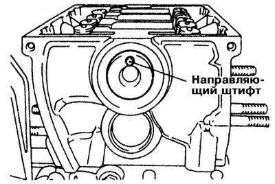
2. When installing the shaft, make sure that it is properly deployed in the head - be guided by the position of the anti-knock finger.
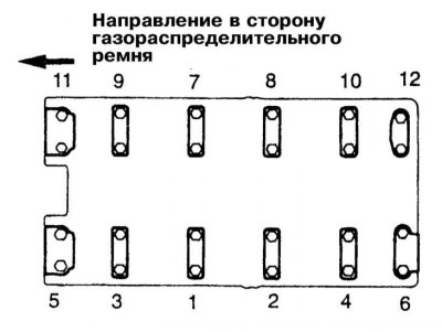
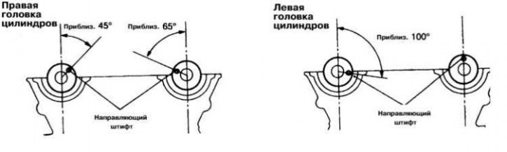
3. Lubricate the seating surfaces of the bearing caps with sealant and install the valve drive mechanism assembly from the head. Following the correct marks in the form of arrows, install the bearing caps. Screw in the bolts for fastening the covers and, acting in a strictly defined order (No. 1, No. 2, No. 1 and No. 4), tighten them to the required torque (10 Nm).
4. Acting in the same order, tighten the bearing cap bolts with a force of 20 Nm.
5. Remove the devices from the rocker arms that secure the hydraulic valve clearance adjusters.
6. Install the camshaft gear.
7. While holding the shaft from turning, use the special tools to tighten the wheel bolt to the required torque (90 Nm).
8. Install the timing belt and cylinder head covers.
9. Having replaced a sealing ring, establish a transitional nozzle of the distributor of ignition.
10. Install the intake manifold pressure chamber support bracket.
11. Having followed the correct alignment of the landing marks, install the ignition distributor assembly on the engine.
12. Connect the negative cable to the battery. Start the engine and check it for signs of leaks.
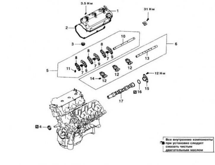
Engines 3.5 l
Removing
1. Details of installing the components of the valve drive mechanism on 3.5L models are shown in the illustration.
2. Disconnect the negative cable from the battery.
If the stereo system installed in the car is equipped with a security code, before disconnecting the battery, make sure that you have the correct combination to activate the audio system!
3. Remove the timing belt (see Section Removing and installing timing cover and timing belt).
4. Remove the cover (And) cylinder heads.
5. Using special clips, fix the hydraulic correctors on the rocker arms of the valve drive. Loosen, but do not completely remove the camshaft bearing cap bolts.
6. Remove the rocker arm assembly with its axles.
7. Remove the camshaft (s).
Installation
1. Lubricate the camshaft (s) thick engine oil and lower it into place in the cylinder head.
2. When installing the shaft, make sure that it is properly deployed in the head - be guided by the position of the anti-knock finger.
3. Install the valve actuator assembly (rocker arms with their axles) and camshaft bearing caps. Screw in the mounting bolts and tighten them with the required force (31 Nm).
4. Install the cover (And) cylinder heads, - do not forget to replace the sealing gasket.
5. Install the timing belt and other components removed for access.
6. Connect the negative cable to the battery. Start the engine and check it for signs of leaks.
Assessment of the degree of wear of the camshaft cams
The height of the camshaft cam determines the amount of valve opening, as a result of which the wear of the cams has a direct impact on the efficiency of the engine.
Cam lift measurement can be done in two ways (depending on the availability of suitable tools).
Determination of the lifting height of the cams using a dial-type meter
1. Determining the height of the cam lift using a plunger-type dial gauge can be done in situ (without removing the shaft from the engine). Measurements are made for each cam separately.
2. For the purpose of ensuring access to a camshaft remove a cover of a head of cylinders.
3. Mount the meter so that its working plunger is directly above the surface of the cam to be tested.
4. Turn the engine so that the camshaft cam turns heel down and reset the meter.
The engine can be cranked remotely using a starter, or manually by using the crankshaft pulley bolt. Remember that the crankshaft can only be turned in the normal direction!
5. Slowly continue to turn the shaft until the pusher is in the maximum lowered position (full valve opening).
6. Read the maximum reading of the device and compare it with the allowable values specified in the Specifications.
7. If the wear of any of the cams is outside the allowable range, the shaft must be replaced complete with valve lifters.
8. When finished checking, remove the gauge and reinstall the cylinder head cover.
Measurement with a micrometer
1. An assessment of the degree of wear of the camshaft cams with a micrometer can only be made after the preliminary dismantling of the shaft.
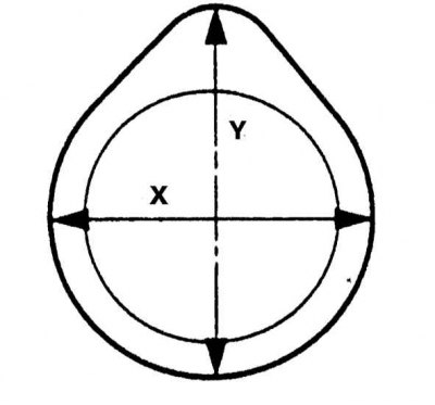
2. The measurement is made in two steps. First, the full working height of the cam is determined (Y), then its width (X) (eccentric base diameter). To determine the height of the cam, subtract the result of the second measurement from the result of the first measurement.
3. Compare the calculation results with the requirements of the Specifications. If any of the cams is worn below the permissible limit, the shaft must be replaced as an assembly with valve lifters.