



MPI Models
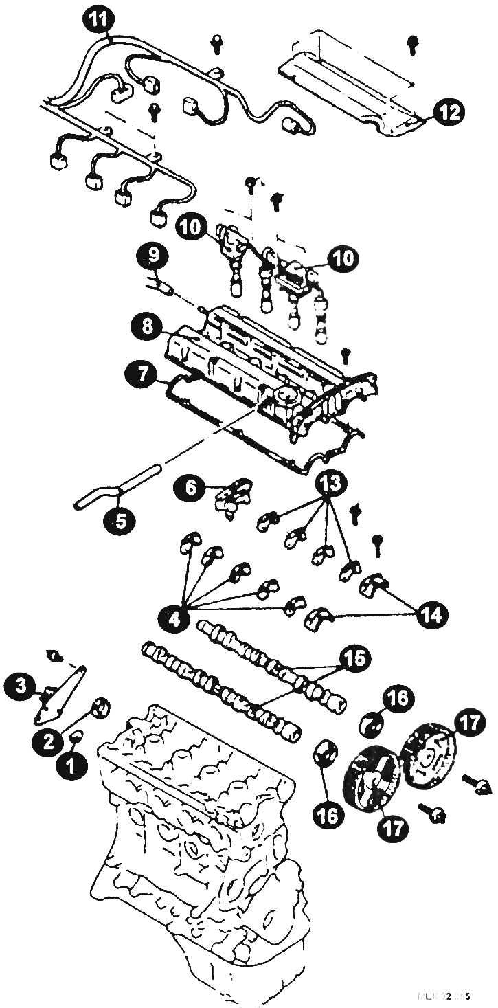
Camshaft Setting Elements. MPI Models
1 - semicircular insert; 2 - oil seal; 3 - ignition system sensor; 4, 13 - camshaft bearing caps; 5 - forced ventilation system branch pipe; 6 - rear cover of camshaft bearings; 7 - gasket; 8 - cylinder head cover; 9 - connection of the crankcase ventilation hose; 10 - ignition coil; 11 - Engine control system harness; 12 - Upper engine cover; 14 - Front timing belt cover; 15 - distribution shaft; 16 - camshaft oil seal; 17 - camshaft gear.
Removal
Disconnect the ground cable from the battery.
Remove the camshaft drive belt.
Remove the top cover.
After unscrewing the bolts, remove the ignition coils together with the spark plug tips.
Remove the crankcase ventilation hose and the forced crankcase ventilation system pipe from the cylinder head cover.
Disconnect the electrical connectors and remove the engine management system wiring harness.
Remove the ignition system malfunction sensor assembly.
Remove the cylinder head cover together with the gasket.
Remove the semicircular insert.
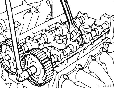
Holding the camshafts with a wrench, unscrew the camshaft gear mounting bolts and remove the wheels.
Remove the camshaft seals.
Remove the O-ring.
After unscrewing the bolts, remove the front camshaft bearing caps.
Loosen the bolts and remove the rear camshaft bearing cover.
Loosen the camshaft cover mounting bolts in several steps, remove the covers and camshafts.
Installation
Installation is carried out in reverse order, taking into account the following:
Coat the camshaft journals and camshaft lobes with engine oil.
Place the camshaft in the cylinder head bed.
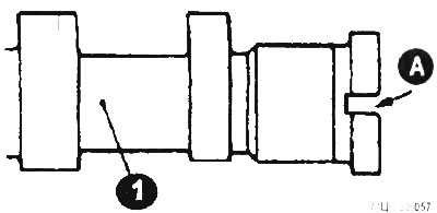
Do not mix up the camshafts. The exhaust camshaft (1) has a slot (A) on its rear end.
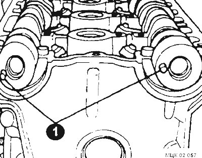
Position the camshaft dowel pins (1) as shown in the figure.
Position the camshaft bearing caps correctly.
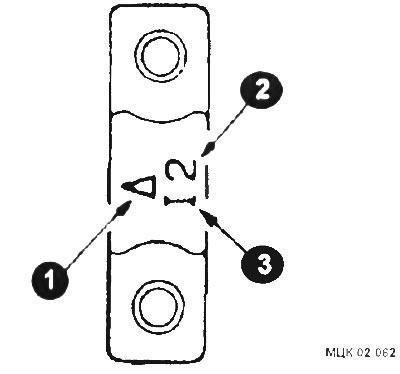
Check the camshaft identification marks and the numbers of the 2 bearing caps, install them taking into account their conformity and the orientation of the "front" mark (1). The inlet camshaft has the identification symbol I (3). The exhaust camshaft has the identification symbol E.
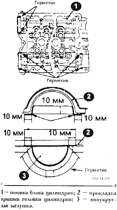
Apply sealant to the designated areas of the cylinder head.
Tighten the camshaft bearing caps in two or three steps. Then tighten the bolts to the final torque.
- Front and rear covers 25 Nm.
- Other caps 12 Nm.
Make sure the valve rocker arms are properly oriented in relation to the valve stems and lifters.
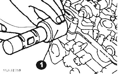
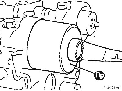
Using a special device (1) or a mandrel made from a pipe, install the seal.
Lubricate the lip (1) of the camshaft oil seal (2) with engine oil.
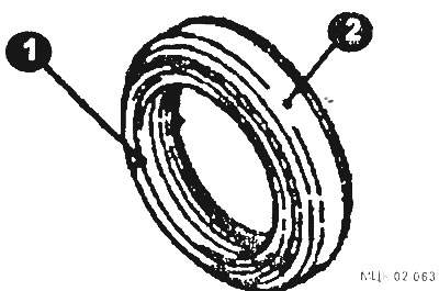
When pressing in the camshaft oil seal, use a special tool.
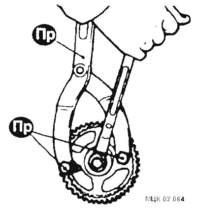
To prevent the pulley from turning, use a special device, and then tighten the bolts to a torque of 90 Nm.
GDI Models
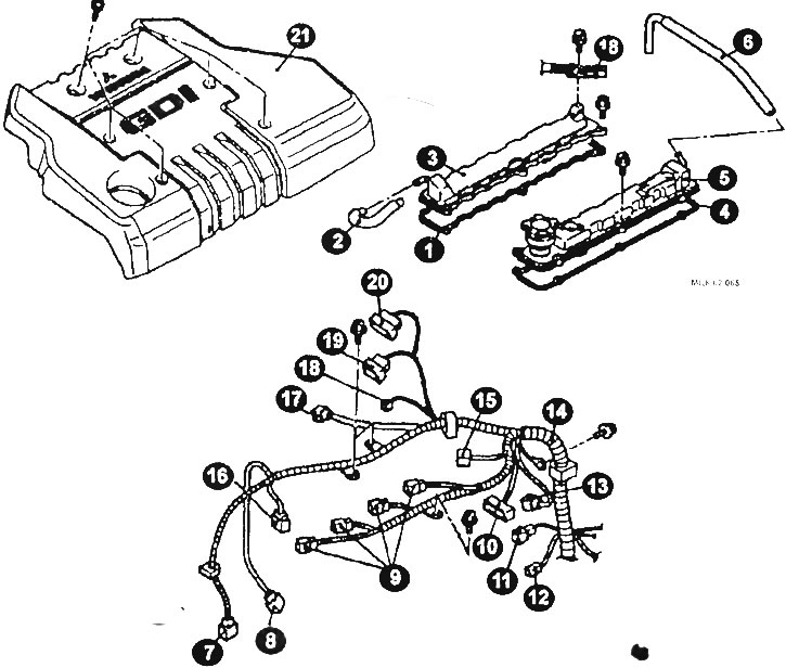
External Engine Components. GDI Models
1, 4 - cylinder head cover gasket; 2 - engine ventilation hose; 3 - cylinder head cover (intake valves); 5 - cylinder head cover (exhaust valves); 6 - engine ventilation hose; 7 - crankshaft position sensor connector; 8 - oxygen sensor connector; 9 - ignition coil connector; 10 - ignition system sensor connector; 11 - coolant temperature sensor connector; 12 - coolant temperature gauge sensor connector; 13 - camshaft position sensor connector; 14 - wiring harness; 13 - wiring harness connector; 16 - fuel pressure sensor connector; 17 - Engine control system harness connector; 18 - exhaust gas recirculation system connector; 19 - throttle position sensor connector; 20 - Throttle servo connector; 21 - upper engine casing.
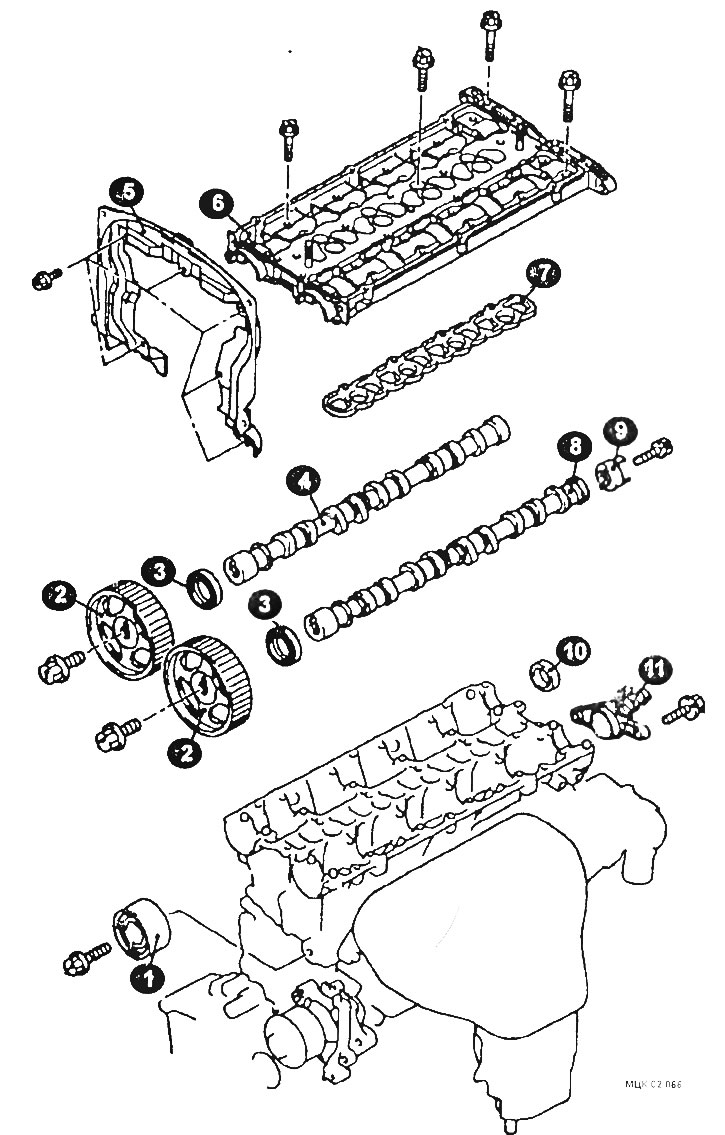
Camshaft mounting elements
1 - idler pulley; 2 - camshaft gear wheel; 3 - oil seal; 4 - intake camshaft; 5 - rear timing belt cover; 6 - camshaft bearing cap; 7 - gasket; 8 - exhaust camshaft; 9 - camshaft position sensor bushing; 10 - plug; 11 - camshaft position sensor support.
Removal
Disconnect the ground cable from the battery.
Remove the top protective cover.
Drain the coolant from the engine cooling system.
Remove the air inlet hose.
After unscrewing the bolts, remove the engine cover.
Disconnect the crankshaft position sensor connector.
Disconnect the connectors of the fuel pressure sensor, the oxygen sensor of the combination of control wiring harness and exhaust gas recirculation wiring harness, the adsorber purge solenoid valve, the throttle position sensor, the throttle control servo of the combination of control wiring harness and nozzle wiring harness, the ignition coil, the ignition system malfunction sensor, the camshaft position sensor, the coolant temperature sensors.
After unscrewing the bolts, disconnect the control wiring harness.
Disconnect the exhaust gas recirculation hose.
Disconnect the positive crankcase ventilation hose.
Remove the ignition coil and intake manifold.
Remove the camshaft drive belt.
Remove the injector wiring harness connector bracket.
After unscrewing the bolts, remove the cylinder head cover from the intake valve side and the gasket.
Remove the exhaust side cylinder head cover and gasket.
Having secured the camshaft gear from turning, unscrew the mounting bolt and remove the camshaft gear.
After unscrewing the bolt, remove the idler pulley.
After unscrewing the bolts, remove the rear upper camshaft drive belt cover.
Remove the camshaft oil seal.
Remove the camshaft position sensor support and plug.
Remove the high pressure fuel pump assembly.
After unscrewing the camshaft cover mounting bolts in several steps, remove the cover.
Remove the camshaft bearing cover gasket.
Remove the intake side camshaft and the exhaust side camshaft.
After unscrewing the bolt, remove the camshaft position sensor bushing.
Installation
Installation is carried out in reverse order, taking into account the following:
Apply engine oil to all moving parts before installation.
Install the camshafts into the cylinder head bed.
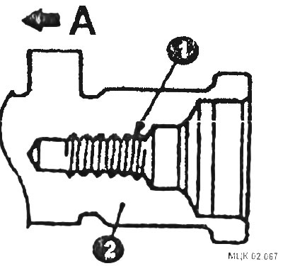
CAUTION: Be careful not to mix up the intake and exhaust camshafts. On the exhaust side of the camshaft (2) there is a hole (1) for the camshaft position sensor bushing mounting bolt.
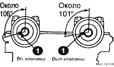
Rotate the camshafts until the pins (1) are in the position shown in the figure.
Tighten the camshaft bearing cap bolts to the specified torques in the sequence shown in the illustration.
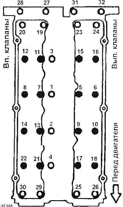
Tightening torques:
- Bolts marked in black - 12 Nm.
- Bolts marked in white - 25 Nm.
Use special tool 1 to press in the plug as shown in the figure
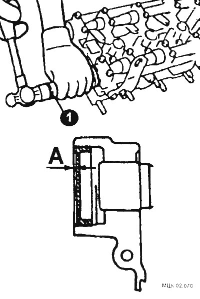
Lubricate the inner surface of the seal lip with engine oil.
Using a tool or a suitable piece of pipe (1), press the seal as shown in the figure.
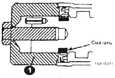
Use the same special tool to lock the camshaft pulley in the same manner as when removing it and tighten the mounting bolt.
After installing the engine cover, tighten the mounting bolts in the sequence shown in the figure.
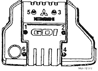
After checking for fuel leaks, install the protective cover.
Fill the engine cooling system with coolant.