



Share with friends:
Electrical equipment and appliances Mitsubishi Colt 5 (CJ)

Technical data of the instrument panel
Technical data of the instrument panel are given in Table 15.1. Table 15.1. Technical data of the instrument panel
Technical data of the instrument panel are given in Table 15.1. Table 15.1. Technical data of the instrument panel

Checking the speedometer
1. Tire pressure must be correct. 2. Place the vehicle on the diagnostic stand and secure the wheels with stops (Figure 15.1). Figure 15.1. Place the vehicle on the...
1. Tire pressure must be correct. 2. Place the vehicle on the diagnostic stand and secure the wheels with stops (Figure 15.1). Figure 15.1. Place the vehicle on the...

Checking the tachometer
1. Connect the tachometer to the crankshaft speed sensor connector (Figure 15.3). A calibrated fluxmeter type tachometer is recommended for checking the tachometer....
1. Connect the tachometer to the crankshaft speed sensor connector (Figure 15.3). A calibrated fluxmeter type tachometer is recommended for checking the tachometer....

Checking the fuel level sensor
1. Remove the fuel level sensor from the fuel tank. 2. Measure the resistance between the fuel level sensor terminal and ground when the float is at the extreme points...
1. Remove the fuel level sensor from the fuel tank. 2. Measure the resistance between the fuel level sensor terminal and ground when the float is at the extreme points...

Checking the resistance of the fuel level indicator
1. Loosen the power supply mounting bolt. 2. Measure the resistance between the connecting terminals with an ohmmeter (Figure 15.5a, b). Nominal value: resistance...
1. Loosen the power supply mounting bolt. 2. Measure the resistance between the connecting terminals with an ohmmeter (Figure 15.5a, b). Nominal value: resistance...

Checking the resistance of the coolant temperature gauge
1. Remove the power supply mounting bolt. 2. Measure the resistance between the connecting terminals with an ohmmeter (Figure 15.6a, b). Nominal resistance value:...
1. Remove the power supply mounting bolt. 2. Measure the resistance between the connecting terminals with an ohmmeter (Figure 15.6a, b). Nominal resistance value:...
Headlight adjustment
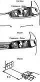
1. Check and adjust tire pressure. 2. Set the distance between the screen and the center of the headlight to 5 m (Figure 15.7). Figure 15.7. Set the distance between the...
1. Check and adjust tire pressure. 2. Set the distance between the screen and the center of the headlight to 5 m (Figure 15.7). Figure 15.7. Set the distance between the...

Headlight and front turn signal
The headlight and front direction indicator are shown in Figure 15.10. Figure 15.10. Headlight and front turn signal: 1 - Multi-function switch; 2 - Hood release handle;...
The headlight and front direction indicator are shown in Figure 15.10. Figure 15.10. Headlight and front turn signal: 1 - Multi-function switch; 2 - Hood release handle;...
Checking the multifunction switch
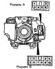
The location of the multi-function switch connectors is shown in Figure 15.11. The test positions are shown in Table 15.3. Figure 15.11. Location of multi-function...
The location of the multi-function switch connectors is shown in Figure 15.11. The test positions are shown in Table 15.3. Figure 15.11. Location of multi-function...

Rear combination light
The rear combination light is shown in Figure 15.12. Figure 15.12. Rear combination light: 1 - Multi-function switch; 2 - Headlight cover (hatchback) or rear trim; 3 -...
The rear combination light is shown in Figure 15.12. Figure 15.12. Rear combination light: 1 - Multi-function switch; 2 - Headlight cover (hatchback) or rear trim; 3 -...

Rheostat — description and verification
The rheostat is shown in Figure 15.13. Figure 15.13. Rheostat: 1 - Decorative switch panel; 2 - Button; 3 - Nut; 4 - Washer; 5 - Rheostat Examination 1. Connect the...
The rheostat is shown in Figure 15.13. Figure 15.13. Rheostat: 1 - Decorative switch panel; 2 - Button; 3 - Nut; 4 - Washer; 5 - Rheostat Examination 1. Connect the...

Hazard warning light switch
The hazard warning light switch is shown in Figure 15.15. Figure 15.15. Hazard warning light switch: 1 - Heater control panel; 2 - Switch lock; 3 - Hazard warning light...
The hazard warning light switch is shown in Figure 15.15. Figure 15.15. Hazard warning light switch: 1 - Heater control panel; 2 - Switch lock; 3 - Hazard warning light...

Engine control unit
The check is carried out by the voltage at the terminals of the engine control unit connector (Figure 15.17 and Table 15.5). Figure 15.17. Engine control unit connector...
The check is carried out by the voltage at the terminals of the engine control unit connector (Figure 15.17 and Table 15.5). Figure 15.17. Engine control unit connector...

Technical characteristics of the heating and air conditioning system
The heating system is characterized by high power and low operating noise. An independent air damper is located on the instrument panel. The system performs the function...
The heating system is characterized by high power and low operating noise. An independent air damper is located on the instrument panel. The system performs the function...

Checking the air conditioning compressor control unit
The air conditioner compressor control unit wiring connector is shown in Figure 15.18. Checking the air conditioner compressor control unit is shown in Table 15.7....
The air conditioner compressor control unit wiring connector is shown in Figure 15.18. Checking the air conditioner compressor control unit is shown in Table 15.7....

Heating system control unit and air conditioner switch
The heating system control unit and the air conditioner switch are shown in Figure 15.19. Figure 15.19. Heating system control unit and air conditioner switch: 1 -...
The heating system control unit and the air conditioner switch are shown in Figure 15.19. Figure 15.19. Heating system control unit and air conditioner switch: 1 -...

Heater and heater radiator
The heater and heater radiator are shown in Figure 15.20. Figure 15.20. Heater and heater radiator: 1 - Mounting brackets; 2 - Middle air duct; 3 - Distribution channel...
The heater and heater radiator are shown in Figure 15.20. Figure 15.20. Heater and heater radiator: 1 - Mounting brackets; 2 - Middle air duct; 3 - Distribution channel...
This section is available on: russian, bulgarian, belarusian, ukrainian, serbian, croatian, romanian, polish, slovak, hungarian
Similar materials for other Mitsubishi models
➤ Electrical equipment: Equipment and devices Mitsubishi Lancer 9 (2000-2007, petrol)
➤ Electrical equipment: Equipment and devices Mitsubishi Galant 5 (1983-1989, petrol)
➤ Electrical equipment: Equipment and devices Mitsubishi L200 4 (2005-2014, diesel)
➤ General information: Salon equipment Mitsubishi Outlander 1 (2003-2008)
➤ Electrical equipment: Equipment and devices Mitsubishi Pajero 4 (2006-2021)
➤ Electrical equipment: Equipment and devices Mitsubishi Carisma (1995-2004)
Link in different formats to this section
TEXTHTMLBB Code
- General information
- User manual
- Specifications
- Gasoline engines
- 4G1 engines until 1995
- 4G1 engines since 1995
- Repair of 4G9 engines
- Cooling system
- Reduced exhaust gas toxicity
- Engine electrical equipment
- Injection system MPI
- Carburetors
- Transmission
- Clutch and drive shafts
- Manual gearbox F4M21/F5M21
- Manual gearbox F4M41
- Automatic gearbox F4A21
- Automatic gearbox F4A41
- Chassis and running gear
- Car suspension
- Steering
- Brake system
- Body
- Exterior (external elements)
- Electrical equipment
- Equipment and devices
- Electrical circuits
- General information
- Maintenance
- Power unit
- Engine in a car
- Engine repair (gasoline)
- Engine repair (diesel)
- Lubrication system
- Cooling system
- Carburetor
- Fuel injection MPI
- Fuel injection GDI
- Emission reduction
- Fuel system (diesel)
- Ignition system
- Exhaust system
- Transmission
- Clutch
- Manual gearbox
- Automatic gearbox
- Drive shafts
- Chassis and running gear
- Chassis malfunctions
- Front suspension
- Rear suspension
- Steering
- Wheels and tires
- Brake system
- Body and interior
- Body elements
- Electrical equipment
- Equipment and devices
- Power devices
- Heating and air conditioning
- Electrical circuits
- General information
- User manual
- Daily care
- Maintenance
- Power unit
- Engine in a car
- Engine overhaul
- Cooling system
- Heater and air conditioner
- Power and exhaust system
- Engine electrical equipment
- Emission reduction
- Transmission
- Mechanical gearbox
- Automatic gearbox
- Clutch and axles
- Chassis and running gear
- Brake system
- Car suspension
- Steering
- Body and interior
- Body and elements repair
- Electrical equipment
- Equipment and devices
- Electrical circuits