



Share with friends:
Electrical equipment of the car engine Mitsubishi Colt 5 (CJ)

Generator and ignition system components (4G1 since 1995)
The generator and ignition system components of 12V SOHC engines are shown in Figure 3.1, 16V SOHC engines on front-wheel drive models (up to 2000) and DOHC engines - in...
The generator and ignition system components of 12V SOHC engines are shown in Figure 3.1, 16V SOHC engines on front-wheel drive models (up to 2000) and DOHC engines - in...

Generator and ignition system (4G9)
The generator and ignition system of the SOHC engine with a distributor are shown in Figure 4.1. Figure 4.1. Generator and ignition system of the SOHC engine with...
The generator and ignition system of the SOHC engine with a distributor are shown in Figure 4.1. Figure 4.1. Generator and ignition system of the SOHC engine with...

Generator — removal and installation, disassembly and assembly
Removal and installation of the generator are shown in Figure 7.1, disassembly and assembly - in Figure 7.2. Figure 7.1. Removing and installing the generator: 1 -...
Removal and installation of the generator are shown in Figure 7.1, disassembly and assembly - in Figure 7.2. Figure 7.1. Removing and installing the generator: 1 -...

Generator — Element Check
Rotor 1. Check the excitation winding for continuity. Make sure that there is continuity between the contact rings. If the resistance is very low, this indicates a short...
Rotor 1. Check the excitation winding for continuity. Make sure that there is continuity between the contact rings. If the resistance is very low, this indicates a short...
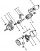
Starter — design description
The direct drive starter is shown in Figure 7.20, and the planetary drive starter is shown in Figure 7.21. Figure 7.20. Direct drive starter: 1, 5, 6 - Bolts; 2 -...
The direct drive starter is shown in Figure 7.20, and the planetary drive starter is shown in Figure 7.21. Figure 7.20. Direct drive starter: 1, 5, 6 - Bolts; 2 -...

Adjusting the Starter Drive Gear Clearance
1. Disconnect the excitation coil wiring from terminal M of the traction relay. 2. Connect the battery between terminal S and terminal M (Figure 7.13). Figure 7.13....
1. Disconnect the excitation coil wiring from terminal M of the traction relay. 2. Connect the battery between terminal S and terminal M (Figure 7.13). Figure 7.13....

Checking the starting force of the starter traction relay
1. Disconnect the excitation coil contacts from terminal M of the traction relay. 2. Connect the battery between terminal S and terminal M (Figure 7.16). Figure 7.16....
1. Disconnect the excitation coil contacts from terminal M of the traction relay. 2. Connect the battery between terminal S and terminal M (Figure 7.16). Figure 7.16....

Checking the starter traction relay
1. Disconnect the excitation coil contacts from terminal M of the traction relay. 2. Connect the battery between terminal S and the vehicle body (Figure 7.17). Figure...
1. Disconnect the excitation coil contacts from terminal M of the traction relay. 2. Connect the battery between terminal S and the vehicle body (Figure 7.17). Figure...

Checking the starter freewheel mechanism
1. While holding the starter with a special tool, connect the battery to the starter. 2. Connect a 100 A ammeter and a carbon plate rheostat between the positive pole of...
1. While holding the starter with a special tool, connect the battery to the starter. 2. Connect a 100 A ammeter and a carbon plate rheostat between the positive pole of...

Checking the reverse stroke of the starter traction relay
1. Disconnect the excitation coil contacts from terminal M of the traction relay. 2. Connect the battery between terminal M and the vehicle body (Figure 7.19). Figure...
1. Disconnect the excitation coil contacts from terminal M of the traction relay. 2. Connect the battery between terminal M and the vehicle body (Figure 7.19). Figure...

Checking the starter manifold
1. Place the anchor on two wooden supports and measure the runout using a dial indicator (Figure 7.22). Limit value: 0.05 mm. Figure 7.22. Checking the collector runout...
1. Place the anchor on two wooden supports and measure the runout using a dial indicator (Figure 7.22). Limit value: 0.05 mm. Figure 7.22. Checking the collector runout...

Checking the electrical conductivity of the starter excitation winding
Check the electrical continuity between the excitation brushes (Figure 7.25) If there is continuity, the excitation winding is OK. Figure 7.25. Checking the electrical...
Check the electrical continuity between the excitation brushes (Figure 7.25) If there is continuity, the excitation winding is OK. Figure 7.25. Checking the electrical...

Checking the starter anchor
1. Place the anchor on the tester. 2 Hold the steel plate parallel and directly above the armature while rotating the armature in the tester (Figure 7.26). If the...
1. Place the anchor on the tester. 2 Hold the steel plate parallel and directly above the armature while rotating the armature in the tester (Figure 7.26). If the...

4G1 Engine Ignition System
Opening the primary circuit current at the ignition coil generates a high voltage on the secondary side of the ignition coil. This high voltage is transmitted by the...
Opening the primary circuit current at the ignition coil generates a high voltage on the secondary side of the ignition coil. This high voltage is transmitted by the...

4G9 Engine Ignition System
The ignition system is equipped with two ignition coils (A and B) and power transistors for the 1st, 4th cylinders and for the 2nd, 3rd cylinders. The interruption of...
The ignition system is equipped with two ignition coils (A and B) and power transistors for the 1st, 4th cylinders and for the 2nd, 3rd cylinders. The interruption of...

Checking the ignition coils of the 4G1 engine
1. Measure the resistance of the primary coil. Measure the resistance between terminals 1 and 2 of the ignition distributor (Figure 7.31). Specified value: 0.5-0.7 Ohm....
1. Measure the resistance of the primary coil. Measure the resistance between terminals 1 and 2 of the ignition distributor (Figure 7.31). Specified value: 0.5-0.7 Ohm....

Checking the 4G1 Engine Power Transistor
Attention! When checking, use an analog voltmeter. Connect the negative lead of the voltmeter to terminal 2 (Figure 7.32). This check is performed very quickly (within...
Attention! When checking, use an analog voltmeter. Connect the negative lead of the voltmeter to terminal 2 (Figure 7.32). This check is performed very quickly (within...

Checking the ignition coil with the engine power transistor 4G9
1. Check the resistance of the secondary coil. Measure the resistance between the high voltage terminals of the ignition coils (Figure 7.33). Specified value: 14-21 kOhm...
1. Check the resistance of the secondary coil. Measure the resistance between the high voltage terminals of the ignition coils (Figure 7.33). Specified value: 14-21 kOhm...

Checking the resistance of the high-voltage wire
Check the resistance of all spark plug wires (Figure 7.35). Maximum permissible value: maximum 22 kOhm. Figure 7.35. Checking the resistance of the high-voltage wire
Check the resistance of all spark plug wires (Figure 7.35). Maximum permissible value: maximum 22 kOhm. Figure 7.35. Checking the resistance of the high-voltage wire

Distributor ignition engine 4G1
Removal and installation of the ignition distributor of the 4G1 engine are shown in Figure 7.36, disassembly and assembly - in Figure 7.37. Figure 7.36. Removing and...
Removal and installation of the ignition distributor of the 4G1 engine are shown in Figure 7.36, disassembly and assembly - in Figure 7.37. Figure 7.36. Removing and...

Camshaft position sensor and crankshaft angle sensor
The camshaft position sensor and crankshaft angle sensor are shown in Figure 7.40. Figure 7.40. Camshaft position sensor and crankshaft angle sensor: 1 - Crankshaft...
The camshaft position sensor and crankshaft angle sensor are shown in Figure 7.40. Figure 7.40. Camshaft position sensor and crankshaft angle sensor: 1 - Crankshaft...

Engine knock sensor 4G9
The 4G9 engine knock sensor is shown in Figure 7.41. Figure 7.41. Engine knock sensor 4G9: 1 - Engine knock sensor
The 4G9 engine knock sensor is shown in Figure 7.41. Figure 7.41. Engine knock sensor 4G9: 1 - Engine knock sensor

Changes in the design of the ignition system since 2001
Engine 4G1 The following maintenance instructions are given in connection with the introduction of the 4G13 SOHC 16-valve fuel-injected engine. The following information...
Engine 4G1 The following maintenance instructions are given in connection with the introduction of the 4G13 SOHC 16-valve fuel-injected engine. The following information...
This section is available on: russian, bulgarian, belarusian, ukrainian, serbian, croatian, romanian, polish, slovak, hungarian
Similar materials for other Mitsubishi models
➤ Power unit: Engine electrical equipment Mitsubishi Galant 5 (1983-1989, petrol)
➤ Power unit: Engine electrical equipment Mitsubishi Pajero 1 and 2 (1982-1999)
➤ Power unit: Engine electrical equipment Mitsubishi Carisma (1995-2004)
Link in different formats to this section
TEXTHTMLBB Code
- General information
- User manual
- Specifications
- Gasoline engines
- 4G1 engines until 1995
- 4G1 engines since 1995
- Repair of 4G9 engines
- Cooling system
- Reduced exhaust gas toxicity
- Engine electrical equipment
- Injection system MPI
- Carburetors
- Transmission
- Clutch and drive shafts
- Manual gearbox F4M21/F5M21
- Manual gearbox F4M41
- Automatic gearbox F4A21
- Automatic gearbox F4A41
- Chassis and running gear
- Car suspension
- Steering
- Brake system
- Body
- Exterior (external elements)
- Electrical equipment
- Equipment and devices
- Electrical circuits
- General information
- Maintenance
- Power unit
- Engine in a car
- Engine repair (gasoline)
- Engine repair (diesel)
- Lubrication system
- Cooling system
- Carburetor
- Fuel injection MPI
- Fuel injection GDI
- Emission reduction
- Fuel system (diesel)
- Ignition system
- Exhaust system
- Transmission
- Clutch
- Manual gearbox
- Automatic gearbox
- Drive shafts
- Chassis and running gear
- Chassis malfunctions
- Front suspension
- Rear suspension
- Steering
- Wheels and tires
- Brake system
- Body and interior
- Body elements
- Electrical equipment
- Equipment and devices
- Power devices
- Heating and air conditioning
- Electrical circuits
- General information
- User manual
- Daily care
- Maintenance
- Power unit
- Engine in a car
- Engine overhaul
- Cooling system
- Heater and air conditioner
- Power and exhaust system
- Engine electrical equipment
- Emission reduction
- Transmission
- Mechanical gearbox
- Automatic gearbox
- Clutch and axles
- Chassis and running gear
- Brake system
- Car suspension
- Steering
- Body and interior
- Body and elements repair
- Electrical equipment
- Equipment and devices
- Electrical circuits