



Share with friends:
4G1 engines up to 1995 car Mitsubishi Colt 5 (CJ)

Technical data of 4G1 engines
Technical data of engines 4G13 12V 1.3 l and 4G15 1.5 l are given in table 2.1. Table 2.1. Technical data of 4G1 engines
Technical data of engines 4G13 12V 1.3 l and 4G15 1.5 l are given in table 2.1. Table 2.1. Technical data of 4G1 engines

Intake manifold (12-valve engines)
The intake manifold of 12-valve carburetor engines is shown in Figure 2.1a, and the intake manifold of 12-valve engines with injection is shown in Figure 2.1b. Figure...
The intake manifold of 12-valve carburetor engines is shown in Figure 2.1a, and the intake manifold of 12-valve engines with injection is shown in Figure 2.1b. Figure...

Exhaust manifold and coolant pump
The exhaust manifold and coolant pump are shown in Figure 2.1c. Figure 2.1 c. Exhaust manifold and coolant pump: 1 - Heat shield for exhaust manifold A; 2 - Bracket; 3 -...
The exhaust manifold and coolant pump are shown in Figure 2.1c. Figure 2.1 c. Exhaust manifold and coolant pump: 1 - Heat shield for exhaust manifold A; 2 - Bracket; 3 -...

Power steering pump drive belt, generator and timing belt
The power steering pump drive belt, generator and timing belt are shown in Figure 2.2. Figure 2.2. Power steering pump drive belt, generator and timing belt: 1 -...
The power steering pump drive belt, generator and timing belt are shown in Figure 2.2. Figure 2.2. Power steering pump drive belt, generator and timing belt: 1 -...

Timing Belt — Removal, Checking and Installation
Removal 1. Mark the direction of rotation of the timing belt to facilitate its reinstallation (Fig. 2.3). Figure 2.3. Mark the direction of rotation of the timing belt...
Removal 1. Mark the direction of rotation of the timing belt to facilitate its reinstallation (Fig. 2.3). Figure 2.3. Mark the direction of rotation of the timing belt...

Checking the alternator drive belt tension
1. Check the tension by pressing the belt and adjust it to the required value. Turn the adjusting bolt clockwise or counterclockwise to increase or decrease the timing...
1. Check the tension by pressing the belt and adjust it to the required value. Turn the adjusting bolt clockwise or counterclockwise to increase or decrease the timing...

Rocker arms, rocker shafts and camshaft
The rocker arms, rocker shafts and camshaft (12-valve engines) are shown in Figure 2.13. Figure 2.13. Rocker arms, rocker shafts and camshaft (12-valve engines): 1, 2 -...
The rocker arms, rocker shafts and camshaft (12-valve engines) are shown in Figure 2.13. Figure 2.13. Rocker arms, rocker shafts and camshaft (12-valve engines): 1, 2 -...

Camshaft — Check
1. Measure the cam height (Figure 2.14). Figure 2.14. Measuring the camshaft cam height 12-valve engines Normal value: inlet valve - 38.75 mm, outlet valve - 39.10 mm....
1. Measure the cam height (Figure 2.14). Figure 2.14. Measuring the camshaft cam height 12-valve engines Normal value: inlet valve - 38.75 mm, outlet valve - 39.10 mm....

Adjusting valve clearance
1. Set the piston of the 1st cylinder to TDC. 2. First, adjust the clearances in the intake 1 and 2 and exhaust 1 and 3 valves (Figure 2.17a, b). Figure 2.17a. Adjusting...
1. Set the piston of the 1st cylinder to TDC. 2. First, adjust the clearances in the intake 1 and 2 and exhaust 1 and 3 valves (Figure 2.17a, b). Figure 2.17a. Adjusting...
Cylinder head and valves (12-valve engines)
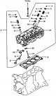
The cylinder head and valves (12-valve engines) are shown in Figure 2.20. Figure 2.20. Cylinder head and valves (12-valve engines): 1 - Cylinder head mounting bolt; 2 -...
The cylinder head and valves (12-valve engines) are shown in Figure 2.20. Figure 2.20. Cylinder head and valves (12-valve engines): 1 - Cylinder head mounting bolt; 2 -...

Cylinder head — check
1. Check the cylinder head deformation with a ruler (Figure 2.21). Cylinder head height: 106.9-107.1 mm. Normal value: 0.05 mm, limit value: 0.2 mm. Figure 2.21....
1. Check the cylinder head deformation with a ruler (Figure 2.21). Cylinder head height: 106.9-107.1 mm. Normal value: 0.05 mm, limit value: 0.2 mm. Figure 2.21....

Valves — Checking
1. Check the valve plate (Figure 2.22). The contact surface of the valve seat should be in the middle of the valve plate and spread evenly over the entire surface....
1. Check the valve plate (Figure 2.22). The contact surface of the valve seat should be in the middle of the valve plate and spread evenly over the entire surface....

Valve spring — check
1. Measure the free length of each spring and replace it if necessary (Figure 2.23). Figure 2.23. Checking the valve spring 12-valve engines Normal value: intake valve -...
1. Measure the free length of each spring and replace it if necessary (Figure 2.23). Figure 2.23. Checking the valve spring 12-valve engines Normal value: intake valve -...

Valve Stem Guide Bushing — Check
1. Measure the clearance between the valve guide and the valve stem (Figure 2.24). If the measured value is greater than the permissible value, the valve guide or the...
1. Measure the clearance between the valve guide and the valve stem (Figure 2.24). If the measured value is greater than the permissible value, the valve guide or the...
Valve seat — inspection and installation
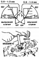
1. Install the valve and measure the valve stem protrusion height (Figure 2.25). If the measured value is greater than the permissible value, replace the valve seat....
1. Install the valve and measure the valve stem protrusion height (Figure 2.25). If the measured value is greater than the permissible value, replace the valve seat....
Oil pan and oil pump
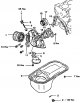
The sump and oil pump are shown in Figure 2.26. Figure 2.26. Oil pan and oil pump: 1 - Oil filter; 2 - Drain plug; 3, 6, 8, 13 - Gaskets; 4 - Pallet; 5 - Oil pump...
The sump and oil pump are shown in Figure 2.26. Figure 2.26. Oil pan and oil pump: 1 - Oil filter; 2 - Drain plug; 3, 6, 8, 13 - Gaskets; 4 - Pallet; 5 - Oil pump...

Oil pan — removal and installation
Removal 1. Drive the special tool between the pan and the cylinder block (Figure 2.27). Remove the pan. Figure 2.27. Removing the tray Installation 2. Clean the contact...
Removal 1. Drive the special tool between the pan and the cylinder block (Figure 2.27). Remove the pan. Figure 2.27. Removing the tray Installation 2. Clean the contact...

Oil pump — inspection and assembly
1. To ensure correct assembly of the oil pump, apply timing marks to the pump rotors or gears (Fig. 2.28). Figure 2.28. To properly assemble the oil pump, apply timing...
1. To ensure correct assembly of the oil pump, apply timing marks to the pump rotors or gears (Fig. 2.28). Figure 2.28. To properly assemble the oil pump, apply timing...
Connecting rod and piston group
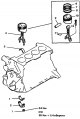
The connecting rod and piston group of the engine is shown in Figure 2.36. Figure 2.36. Connecting rod and piston group of the engine: 1 - Nut; 2 - Connecting rod cover;...
The connecting rod and piston group of the engine is shown in Figure 2.36. Figure 2.36. Connecting rod and piston group of the engine: 1 - Nut; 2 - Connecting rod cover;...

Piston rings — check
1. Check the piston rings for excessive wear, damage or breaks and replace them with new ones if defects are found. If the piston was replaced, the piston rings must...
1. Check the piston rings for excessive wear, damage or breaks and replace them with new ones if defects are found. If the piston was replaced, the piston rings must...

Connecting rod bearings — check
1. Inspect the connecting rod bearings for visible damage and excessive wear. If scratches, nicks, or excessive contact are found, replace the bearings. If severe wear...
1. Inspect the connecting rod bearings for visible damage and excessive wear. If scratches, nicks, or excessive contact are found, replace the bearings. If severe wear...

Compression rings — installation
1. To install compression rings, use special pliers (Figure 2.40). Figure 2.40. Installing compression rings Attention! Please note that the rings have different shapes....
1. To install compression rings, use special pliers (Figure 2.40). Figure 2.40. Installing compression rings Attention! Please note that the rings have different shapes....

Oil scraper ring — installation
1. Insert the oil scraper ring nozzle into the groove under the piston ring. Attention! The rings and the sprayer can be installed in any direction (Figure 2.41). Figure...
1. Insert the oil scraper ring nozzle into the groove under the piston ring. Attention! The rings and the sprayer can be installed in any direction (Figure 2.41). Figure...

Connecting Rod Bearing Cap — Installation
1. Pay attention to the applied marks and install the bearing cap on the connecting rod. If you use a new connecting rod without markings, pay attention to the fact that...
1. Pay attention to the applied marks and install the bearing cap on the connecting rod. If you use a new connecting rod without markings, pay attention to the fact that...
Installing connecting rod bearings
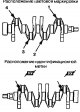
1. Select the liners according to the marks or color coding applied to the crankshaft and the lower connecting rod head (Table 4.2 and Figure 2.45a-c). Table 4.2....
1. Select the liners according to the marks or color coding applied to the crankshaft and the lower connecting rod head (Table 4.2 and Figure 2.45a-c). Table 4.2....

Crankshaft, flywheel and drive disk
The crankshaft, flywheel and drive disk are shown in Figure 2.46. Figure 2.46. Crankshaft, flywheel and drive disk: 1 - Flywheel mounting bolt (cars with manual...
The crankshaft, flywheel and drive disk are shown in Figure 2.46. Figure 2.46. Crankshaft, flywheel and drive disk: 1 - Flywheel mounting bolt (cars with manual...

Crankshaft — installation
1. Measure the outside diameter of the main bearing journal and the inside diameter of the main bearing (Figure 2.47a, b). If the difference is greater than the...
1. Measure the outside diameter of the main bearing journal and the inside diameter of the main bearing (Figure 2.47a, b). If the difference is greater than the...

Flywheel — installation
1. Check the flywheel runout (Figure 2.48). Maximum permissible value: 0.13 mm. Figure 2.48. Checking the flywheel runout
1. Check the flywheel runout (Figure 2.48). Maximum permissible value: 0.13 mm. Figure 2.48. Checking the flywheel runout

Crankshaft Main Bearing Shells — Installation
1. All upper bearings, except the middle one, have grooves. The middle bearings with flanges do not have grooves. 2. The lower liners are all without grooves. 3. Select...
1. All upper bearings, except the middle one, have grooves. The middle bearings with flanges do not have grooves. 2. The lower liners are all without grooves. 3. Select...

Cylinder Block — Design Description
The cylinder block is shown in Figure 2.49. Figure 2.49. Cylinder block: 1, 2, 3, 4, 5 - Brackets; 6 - Cylinder block; 7 - Oil pressure sensor.
The cylinder block is shown in Figure 2.49. Figure 2.49. Cylinder block: 1, 2, 3, 4, 5 - Brackets; 6 - Cylinder block; 7 - Oil pressure sensor.

Cylinder Block — Checking and Repairing
Examination 1. Using a thin ruler and a measuring gauge, check the deformation of the upper part of the cylinder block (Figure 2.50). It is important that the surfaces...
Examination 1. Using a thin ruler and a measuring gauge, check the deformation of the upper part of the cylinder block (Figure 2.50). It is important that the surfaces...

Tightening torques for elements and parts of 4G1 engines
Tightening torques for elements and parts of 4G1 engines Name Tightening torque, Nm Coolant pump pulley mounting bolt 9 Crankshaft Groove Pulley Fastening Bolt 14...
Tightening torques for elements and parts of 4G1 engines Name Tightening torque, Nm Coolant pump pulley mounting bolt 9 Crankshaft Groove Pulley Fastening Bolt 14...
This section is available on: russian, bulgarian, belarusian, ukrainian, serbian, croatian, romanian, polish, slovak, hungarian
Similar materials for other Mitsubishi models
➤ Power unit: Petrol engines 4G1 Mitsubishi Space Star (1998-2005)
Link in different formats to this section
TEXTHTMLBB Code
- General information
- User manual
- Specifications
- Gasoline engines
- 4G1 engines until 1995
- 4G1 engines since 1995
- Repair of 4G9 engines
- Cooling system
- Reduced exhaust gas toxicity
- Engine electrical equipment
- Injection system MPI
- Carburetors
- Transmission
- Clutch and drive shafts
- Manual gearbox F4M21/F5M21
- Manual gearbox F4M41
- Automatic gearbox F4A21
- Automatic gearbox F4A41
- Chassis and running gear
- Car suspension
- Steering
- Brake system
- Body
- Exterior (external elements)
- Electrical equipment
- Equipment and devices
- Electrical circuits
- General information
- Maintenance
- Power unit
- Engine in a car
- Engine repair (gasoline)
- Engine repair (diesel)
- Lubrication system
- Cooling system
- Carburetor
- Fuel injection MPI
- Fuel injection GDI
- Emission reduction
- Fuel system (diesel)
- Ignition system
- Exhaust system
- Transmission
- Clutch
- Manual gearbox
- Automatic gearbox
- Drive shafts
- Chassis and running gear
- Chassis malfunctions
- Front suspension
- Rear suspension
- Steering
- Wheels and tires
- Brake system
- Body and interior
- Body elements
- Electrical equipment
- Equipment and devices
- Power devices
- Heating and air conditioning
- Electrical circuits
- General information
- User manual
- Daily care
- Maintenance
- Power unit
- Engine in a car
- Engine overhaul
- Cooling system
- Heater and air conditioner
- Power and exhaust system
- Engine electrical equipment
- Emission reduction
- Transmission
- Mechanical gearbox
- Automatic gearbox
- Clutch and axles
- Chassis and running gear
- Brake system
- Car suspension
- Steering
- Body and interior
- Body and elements repair
- Electrical equipment
- Equipment and devices
- Electrical circuits