



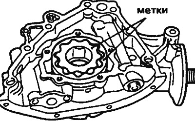
Figure 2.28. To properly assemble the oil pump, apply timing marks to the pump rotors or gears
Examination
Gear pump
2. Check the clearance between the internal gear teeth and the segment (Figure 2.29). Normal value: 0.21-0.34 mm. Limit value: 0.5 mm.
(The material was borrowed from the website: mitsubishiman.ru)
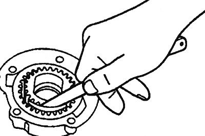
Figure 2.29. Checking the clearance between the internal gear teeth and the segment
3. Check the clearance between the outer gear teeth and the segment (Figure 2.30).
Normal value: 0.22-0.44 mm. Limit value: 0.6 mm.
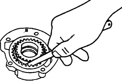
Figure 2.30. Checking the clearance between the outer gear teeth and the segment
4. Check the axial clearance of the pump (Figure 2.31). Normal value: 0.04-0.10 mm. Limit value: 0.15 mm.
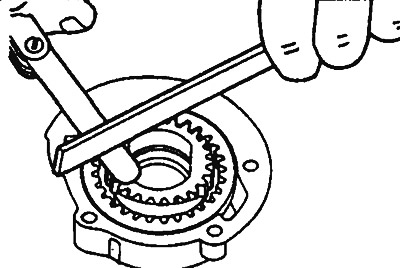
Figure 2.31. Checking the axial clearance of the gear oil pump
5. Check the clearance between the outer gear and the oil pump body (Figure 2.32). Normal value: 0.1-0.20 mm. Limit value: 0.3 mm.
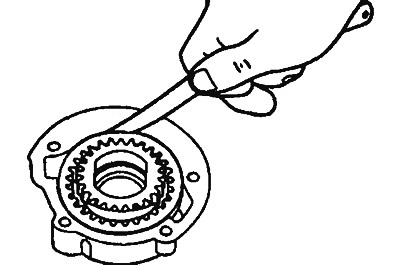
Figure 2.32. Checking the clearance between the outer gear and the oil pump housing
Rotary pump
6. Check the radial clearance (Figure 2.33). Normal value: 0.06-0.18 mm. Limit value: 0.35 mm.
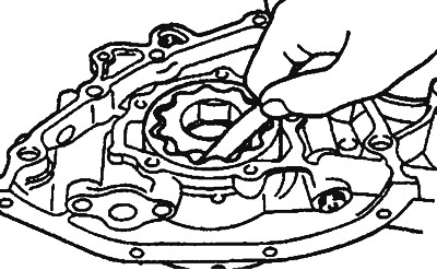
Figure 2.33. Checking the radial clearance of the rotary oil pump
7. Check the axial clearance (Figure 2.34). Normal value: 0.04-0.10 mm. Limit value: 0.2 mm.
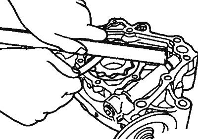
Figure 2.34. Checking the axial clearance of the rotary oil pump
8. Check the clearance between the outer rotor and the pump body (Figure 2.35). Normal value: 0.10-0.18 mm. Limit value: 0.35 mm.
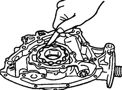
Figure 2.35. Checking the clearance between the outer rotor and the pump casing