



Engine 2.0 l
Attention! Please read the procedure for removing the timing belt.
Engine Coolant Pump 2.0L
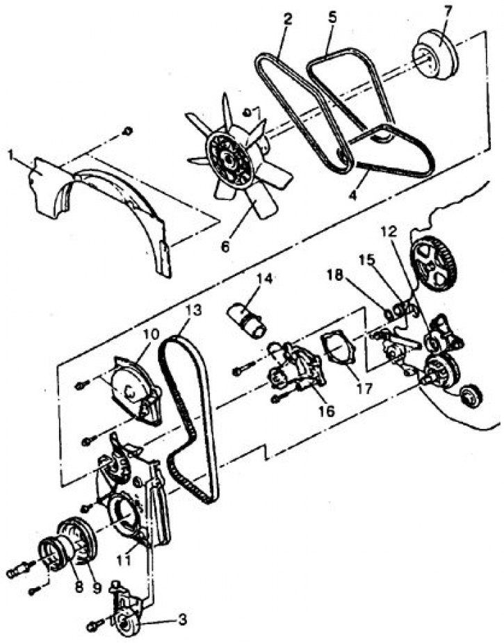
1. Casing; 2–5. Belts; 6. Impeller with clutch; 7, 8, 9. Pulleys; 10. Top cover; 11. Bottom cover; 12. Tensioner; 13. Toothed belt; 14. Hose; 15. Branch pipe; 16. Pump; 17. Gasket; 18. Ring
Removal
1. Disconnect the battery from ground.
2. Set the piston of the 1st cylinder to TDC of the compression stroke.
3. Drain the liquid.
4. Remove the upper fan shroud.
5. Remove all belts by loosening the mounting bolts of the corresponding unit.
6. Remove the fan and clutch.
7. Remove the pump pulley.
8. Loosen the bolts and remove the pulleys from the crankshaft nose.
9. Remove the covers, loosen the tensioner and, without disturbing the crankshaft installation, remove the toothed belt, marking the direction of rotation on it with chalk.
10. Disconnect the hose, unscrew the bolts and remove the pump.
11. Check the condition of the pump. If damage to the housing or leakage through the inspection hole is detected, replace the pump (cannot be repaired). Clean the pump split surface.
Installation
Installation is carried out in reverse order, taking into account the following:
- replace the pump gasket and o-ring by wetting it with water or liquid (not oil);
- tighten the pump mounting bolts in 2 stages: bolts marked "4"
- with a torque of 14 Nm, bolts marked "7" – 24 Nm.;
- install the timing belt so that there is no slack between the crankshaft and oil pump sprockets, or the oil pump and camshaft sprockets. Loosen the tensioner bolt and turn the crankshaft so that the camshaft sprocket moves 2 teeth from the timing mark. If the belt on the camshaft becomes loose, take up the slack by slightly moving the tensioner down. Tighten the lower then upper tensioner bolts;
- tighten the belt cover bolts to 11 N·m, the crankshaft bolt to 120 N·m, the small pulley bolt to 25 N·m, the pulley and impeller nuts on the cooling pump to 11 N·m.
When finished, warm up the engine, restore the fluid level and adjust the belts.
Diesel
Diesel Coolant Pump
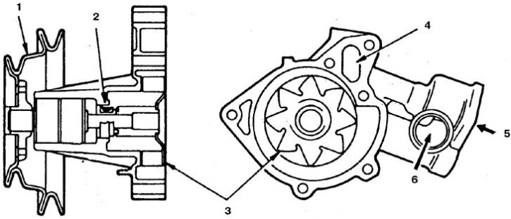
1. Pulleys; 2. Seal; 3. Impeller; 4. Bypass channel; 5. From the radiator; 6. To the branch pipe
Removal and installation
1. Disconnect the battery from ground.
2. Drain the liquid.
3. Disconnect the hose from the pump.
4. Remove the fan, clutch and pulley.
5. Loosen the bolts and remove the pump.
6. Check the freedom of rotation of the roller and the condition of the seals. If damage to the housing or leakage through the ventilation hole is detected, replace the pump (cannot be repaired).
7. Installation is carried out in reverse order. Replace the gasket.
2.4L Engine
Removal
1. Disconnect the battery from ground.
2. Drain the liquid.
3. Remove the upper fan cover.
4. Remove all belts.
5. Disconnect the hose from the pump.
6. Loosen the bolts and remove the pulleys from the crankshaft nose.
7. Set the piston of the 1st cylinder to TDC of the compression stroke, remove the covers and the toothed belt.
8. Unscrew the bolts, paying attention to their location, and remove the pump.
9. Clean the split surface of the pump, check its condition. If damage or leakage is detected, replace the pump (cannot be repaired).
Installation
Installation is carried out in reverse order, taking into account the following:
- replace the pump gasket and o-ring by wetting it with water or liquid (not oil);
- tighten the pump mounting bolts to a torque of 13 Nm.;
- install and tension the timing belt in the order specified for the 2.0L engine (see above).
2.6L Engine
Engine Coolant Pump 2.6L
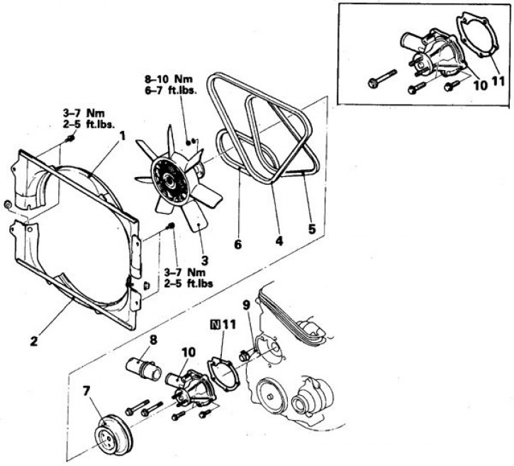
1, 2. Casing; 3. Impeller with coupling; 4–6. Belts; 7. Pulley; 8. Radiator hose; 9. Heater hose; 10. Pump; 11. Gasket
Removal and installation
1. Disconnect the battery from ground.
2. Drain the liquid.
3. Disconnect the radiator hose from the pump.
4. Remove the upper fan shroud. Remove the fan and coupling, store the fan in the working position.
5. Remove the drive belts.
6. Remove the pump pulley.
7. Disconnect the heater hose from the pump.
8. Unscrew the bolts, paying attention to their location, and remove the pump.
9. Clean the split surface of the pump, check its condition. If damage or leakage is detected, replace the pump (moistening of the inspection hole is allowed).
10. Installation is carried out in reverse order. Replace the gasket. Tighten the pump mounting bolts to a torque of 21 Nm in several stages. Tighten the belts.
Engine 3.0 l
Caution: When removing the pump on 6-cylinder engines, mark all bolts that you install in their places. The crankshaft sprocket is pressed off using a special puller.
Engine Coolant Pump 3.0L
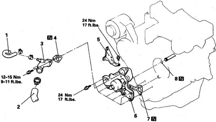
1. Bypass hose; 2. Radiator hose; 3. Impeller with coupling; 4, 7. Gasket; 5. Tensioner bracket; 6. Pump; 8. Ring
Removal and installation
1. Perform decompression. To do this, disconnect the connector at the rear of the fuel tank, start the engine and after it stops, turn off the ignition.
2. Disconnect the battery from ground.
3. Drain the fluid, remove the thermostat, disconnect the upper radiator hose, the bypass hose, remove the fan shroud.
(Original version of the article on the website mitsubishiman.ru)
4. Remove the fan and coupling.
5. Remove the drive belts.
6. Remove the pump pulley.
7. Remove the power steering pump and brackets. Move the pump to the side without disconnecting it from the line.
8. Remove the tensioner bracket.
9. Remove the air conditioning compressor. Move the unit to the side without disconnecting it from the line and secure it. Remove the compressor bracket.
10. Remove the fan bracket.
11. Set the piston of the 1st cylinder to TDC of the compression stroke, remove the covers, loosen the tensioner bolts and remove the toothed belt, marking the direction of rotation.
12. Unscrew the bolts, paying attention to their location, and remove the pump.
13. Remove the branch pipe and clean the split surface of the pump, check its condition. If damage or leakage is detected, replace the pump.
14. Installation is carried out in reverse order. Replace all removed gaskets and seals. Install and adjust the belts according to the description in the relevant sections. Tighten the pump mounting bolts to 27 Nm.
Engine 3.5 l
Engine Coolant Pump 3.5L
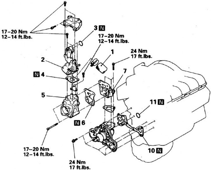
1. Radiator hose; 2. Outlet pipe; 3, 11. Ring; 4, 6, 10. Gasket; 5. Thermostat; 7. Transition station
Removal and installation
1. Perform decompression. To do this, disconnect the connector at the rear of the fuel tank, start the engine and after it stops, turn off the ignition.
2. Disconnect the battery from ground.
3. Drain the liquid.
4. Remove the radiator with the upper hose and the fan shroud.
5. Remove the generator, battery and tray.
6. Remove the lower engine shields.
7. Remove the fan, coupling and pump pulley.
8. Remove the air conditioning compressor. Move the unit to the side without disconnecting it from the line and secure it. Remove the compressor bracket.
9. Remove the power steering pump and brackets. Move the pump to the side without disconnecting it from the line.
10. Remove the front covers and disconnect the connector from the crankshaft speed sensor.
11. Use a puller to press off the crankshaft pulley.
12. Remove the timing belt. To do this, follow these steps:
- align the marks on the sprockets and on the cylinder head;
- loosen the tensioner bolt and mark the direction of rotation on the belt.
13. Remove the tensioner, roller and lever.
14. Remove the upper pipe and thermostat from the pump.
15. Clean the split surface of the pump, check its condition. If damage or leakage is detected, replace the pump.
16. Installation is carried out in reverse order. Replace the removed gaskets and seals. Install and adjust the belts according to the description in the relevant sections. Tighten the pump mounting bolts to a torque of 24 Nm in 2–3 stages, moving around the periphery. Press the pulley onto the crankshaft using a special tool.