



Contents: Lubrication system parts ⤓ Lubrication system diagram of the…⤓ Checking the clearances in the oil…⤓ Removal ⤓ Assembly ⤓
Lubrication system parts
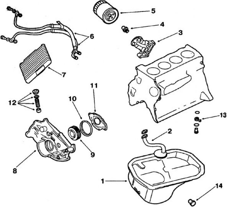
1. Oil pan; 2. Oil receiver; 3. Oil filter bracket; 4. Oil filter bypass valve; 5. Oil filter; 6. Reinforced hose; 7. Oil radiator; 8. Lower cylinder block cover; 9. Oil pump drive gear; 10. Oil pump driven gear; 11. Oil pump cover; 12. Pressure reducing valve; 13. Nozzles for cooling the piston bottom; 14. Oil drain plug
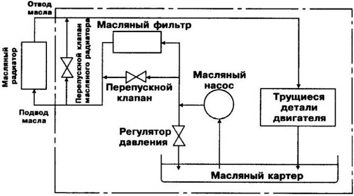
Lubrication system diagram of the 4D56T engine
Checking the clearances in the oil pump
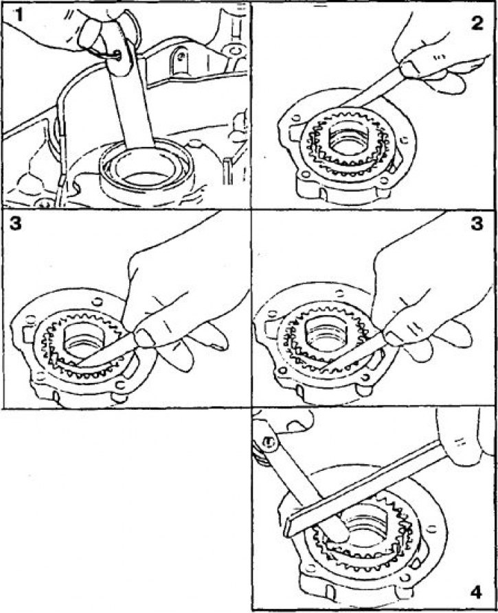
1. Checking the clearance between the outer diameter of the drive gear and the pump housing ratchet
2. Checking the clearance between the outer diameter of the driven gear and the bore of the pump body
3. Checking the clearance between the gear teeth and the separating sickle
4. Checking the clearance between the ends of the gears and the plane of the pump body
The engine has a pressure lubrication system created by a gear pump driven directly by the crankshaft (see figure Lubrication system parts).
In addition to the oil pump, the lubrication system includes an oil filter and an oil radiator, as well as nozzles installed at the base of each cylinder, through which oil is sprayed to cool the piston crowns.
Gear type oil pump with internal gearing.
Oil pressure at idle, kgf/cm² – 2.
Response pressure of the oil pressure indicator lamp sensor, kgf/cm² – 0.3.
Opening pressure of the injector valves for cooling the piston bottoms, kgf/cm² – 2.
Attention! On 4D56T engines, instead of a gear oil pump, a pump with trochoidal engagement is used, providing higher performance.
Opening pressure of the oil filter pressure reducing valve, kgf/cm² – 1.5.
Stroke of the oil radiator thermostat valve, mm:
- at ambient temperature: 34.5;
- immersed in oil heated to 100°C: 40.
Oil cooling system opening temperature: 80°C.
The replaceable filter element is equipped with a built-in bypass valve.
When operating under normal conditions, the filter element must be replaced every 10,000 km; when operating under severe conditions, every 6,000 km.
Opening pressure of the bypass valve, kgf/cm² – 5.5.
Filter element brand: Mitsubishi.
Attention! The 4D56T engines are equipped with a new Mitsubishi oil filter with two cleaning stages.
The plate-type oil radiator is installed in front of the 4D56T engine cooling system radiator.
Cooling capacity, kJ/h: 12.98.
The lubrication system includes a drain line with a bypass valve that directs oil to the oil cooler (see figure Lubrication system diagram of the 4D56T engine).
This ensures a continuous supply of oil to the rubbing parts of the engine in the event of clogging or obstruction of the oil radiator. The opening of the bypass valve, mounted on the side of the engine, is determined only by the oil temperature. With the valve open, this reduces the time it takes for the oil to warm up when starting a cold engine.
Removal
1. To remove the oil pump, remove the lower cylinder block cover.
2. Remove the oil pump drive gear.
3. Remove the oil pump cover. Remove the driven and driving gears of the oil pump and apply timing marks to the gears so that they can be returned to their original position during assembly.
4. To check the technical condition, make sure that the gear teeth have no signs of wear or damage.
The material was copied from the website (www.mitsubishiman.ru)
5. Using a set of feeler gauges and the data given in the subsection, check the gaps (see figure Checking clearances in the oil pump):
- clearance between the teeth of the drive gear and the separating sickle, mm: 0.22–0.35;
- clearance between driven gear teeth and separating sickle, mm: 0.12–0.22;
- clearance between the ends of the gears and the plane of the pump body, mm: 0.04–0.10;
- clearance between the outer diameter of the driven gear and the bore of the pump body, mm: 0.12–0.22;
- clearance between the outer diameter of the drive gear and the bore of the pump body, mm: 0.03–0.09.
Assembly
The oil pump is assembled in the reverse order of disassembly, observing the marks made on the gears during disassembly.