



The interruption of the primary circuit current from ignition coil A induces a high voltage in the secondary circuit of coil A. This high voltage is transmitted to the spark plugs of cylinders 1 and 4 to create an ignition spark. If, at the time when both spark plugs create a spark, one cylinder is operating in the compression stroke, the other cylinder is in the exhaust stroke, ignition of the compressed fuel-air mixture will occur only in the cylinder that is in the compression stroke.
The same process occurs in ignition coil B. If the current in its primary circuit is interrupted, the high voltage created by this is supplied to the spark plugs of the 2nd and 3rd cylinders. The electronic engine control unit alternately switches on and off the two power transistors in the ignition coils. Due to this, the primary circuit current in both coils is alternately interrupted, and ignition occurs in the following order: cylinders 1-3-4-2.
The engine control unit determines which ignition coil is activated by a pulse sent by the camshaft position sensor and the crankshaft angle sensor. If the engine is cold or the vehicle is operated at high altitude, the ignition timing is advanced slightly to optimally adapt the power to the given operating conditions.
If the engine detonates, the ignition timing slowly retards until the knocking noise stops.
The ignition system of the 4G9 engine is shown in Figure 7.30.
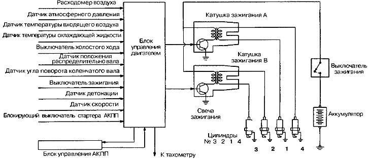
Figure 7.30. 4G9 engine ignition system
(The text of the article was taken from the website: mitsubishiman.ru)
Table 7.1b. Technical data of ignition coils
| Engine | 4G1 | 4G9 |
| Ignition type | Closed single coil with integrated distributor | Closed Binary Ignition Coil |
Table 7.1c. Ignition coil
| Engine | 4G1 | 4G9 except MW | 4G9MW |
| Primary coil resistance | 0.5-0.7 Ohm | — | — |
| Secondary coil resistance | 15-22 Ohm | 14-21 Ohm | 20-30 Ohm |