



Contents: Checking the secondary resistance of…⤓ Checking the primary coil for…⤓ Checking the ignition system failure…⤓ Ignition coils ⤓ Engine camshaft position sensor 4G1 ⤓ Crankshaft position sensor ⤓ Knock sensor ⤓
Engine 4G1
The following maintenance instructions are given in connection with the introduction of the 4G13 SOHC 16-valve fuel-injected engine. The following information applies to the 4G13 engine:
- an ignition system with two coils and no distributor was introduced;
- spark plug changed;
- added ignition system failure sensor;
- added a knock sensor.
Engine 4G9
Added ignition system failure sensor. Changed crankshaft position sensor. Other items remain unchanged.
Checking the secondary resistance of the ignition coil with a power transistor on a 4G1 engine
Measure the resistance between the high voltage terminals of the ignition coil (Figure 17.10). Nominal value: 11.7-14.3 kOhm.
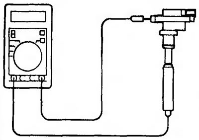
Figure 17.10. Checking the secondary resistance of the ignition coil with a power transistor on a 4G1 engine
Checking the primary coil for continuity and checking the power transistor
The conductivity test of the primary coil and the power transistor test are shown in Figure 17.11.
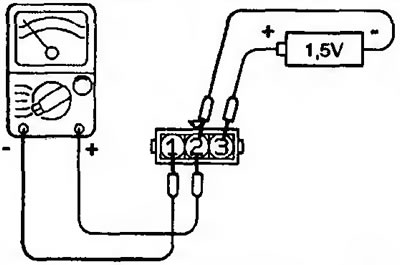
Figure 17.11. Checking the conductivity of the primary coil and checking the power transistor

Checking the ignition system failure sensor
Check that the resistance between terminals 3 and 4 is within the rated value (Figure 17.12). Nominal value: 0.1 ohm or less.
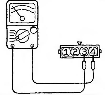
Figure 17.12. Checking the ignition system failure sensor
Ignition coils
The ignition coils of the 4G1 engine are shown in Figure 17.13.
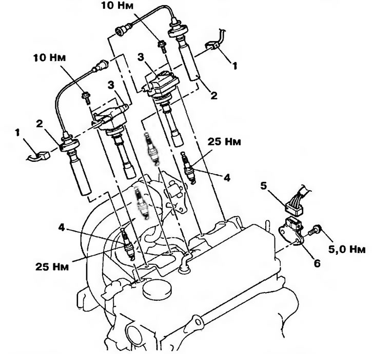
Figure 17.13. Ignition coils of the 4G1 engine: 1 - Ignition coil wiring connector; 2 - Ignition coil high voltage wire; 3 - Ignition coils; 4 - Spark plugs; 5 - Ignition system failure sensor wiring connector; 6 - Ignition system failure sensor
Engine camshaft position sensor 4G1
The camshaft position sensor of the 4G1 engine is shown in Figure 17.14.
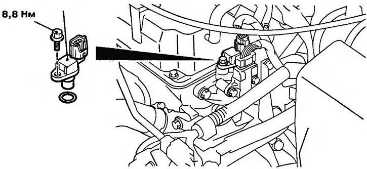
Figure 17.14. Crankshaft position sensor of the 4G1 engine
Crankshaft position sensor
The crankshaft position sensor of the 4G1 engine is shown in Figure 17.15, and of the 4G9 engine - in Figure 17.16.
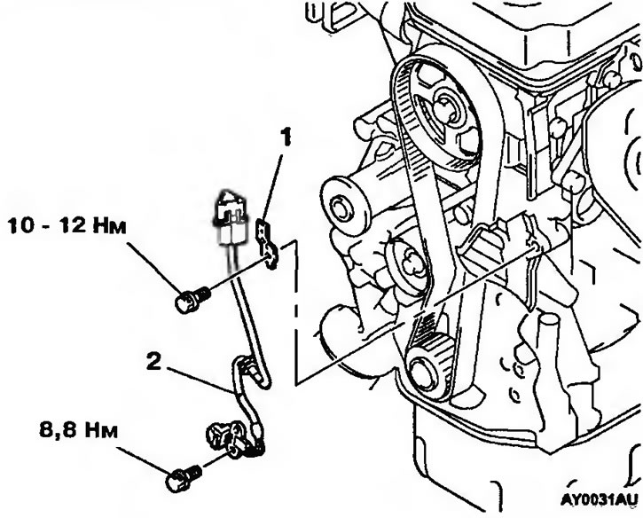
Figure 17.15. Crankshaft position sensor of the 4G1 engine: 1 - Crankshaft position sensor mounting bracket; 2 - Crankshaft position sensor
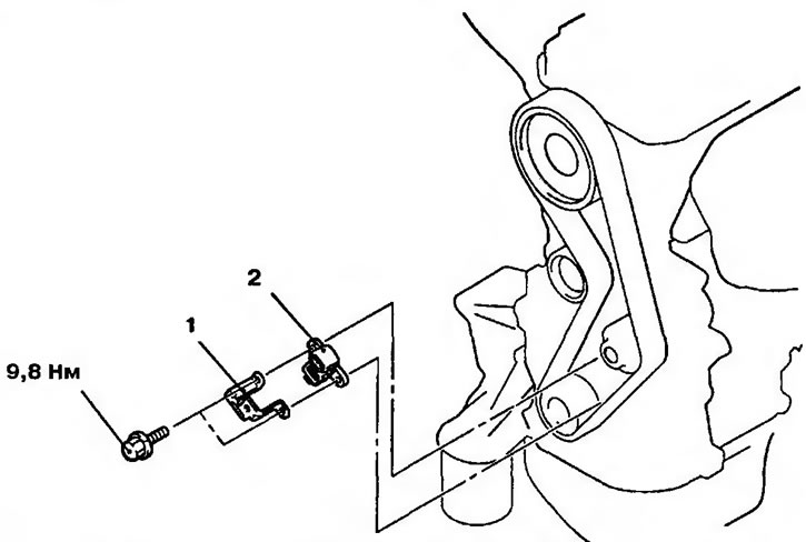
Figure 17.16. Crankshaft position sensor of the 4G9 engine: 1 - Crankshaft position sensor mounting bracket; 2 - Crankshaft position sensor
Knock sensor
The 4G1 engine knock sensor is shown in Figure 17.17.
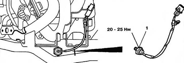
Figure 17.17. Engine knock sensor 4G1: 1 - Knock sensor