
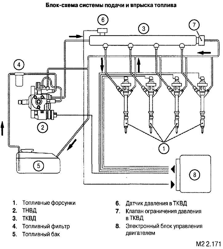
- fuel injectors;
- high pressure fuel pump;
- high pressure fuel manifold;
- fuel tank;
- fuel filter.
General characteristics of the fuel system
| Fuel tank capacity, l | 75 |
| fuel pump type | Fuel pump double plunger |
| Fuel filter type | Filter with replaceable filter element |
| Type of fuel injectors | With electromagnetic drive |
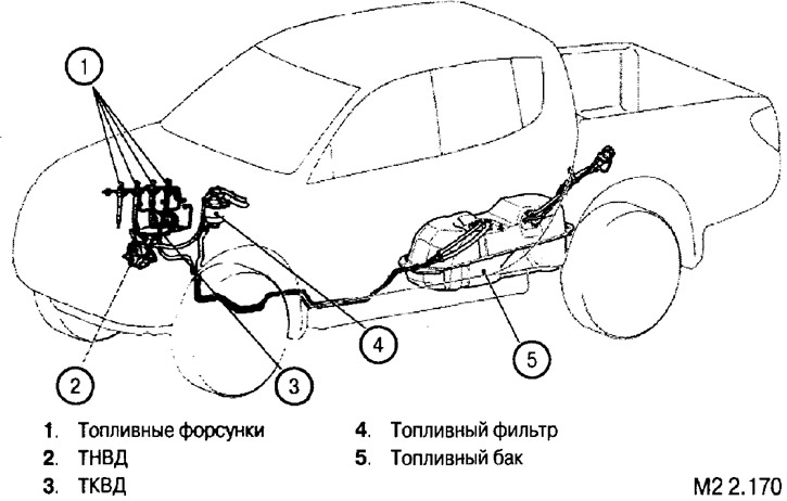
The layout of the elements of the fuel system in the car
Block diagram of the fuel supply and injection system
Diesel fuel injection system with common rail high pressure fuel rail
The main distinguishing feature of the Common rail system is the presence of a storage tank - a high-pressure fuel manifold (further - TKVD), in which fuel is supplied under high pressure (typically 20 to 180 MPa). From the TKVD, fuel enters the injectors. The opening of the injector valve occurs due to the energy of the fuel pressure. The valve opening mechanism is designed in such a way that when a control pulse is applied to the electromagnet installed in the nozzle, the control valve opens. Opening this valve causes fluid to flow into the nozzle channels. The resulting pressure difference causes the nozzle valve needle to rise.
Pulse signals with the required pulse duration are supplied from the electronic engine control unit (further - ECM) to the injectors. The amount of fuel supplied by the injectors depends on the pulse duration and pressure in the HPTC.
The pressure of the fuel injected into the HPTC is maintained by a valve that regulates the fuel supply to the injection pump inlet, which operates on a signal from the ECM. generates a pressure control signal in the HPC based on information coming from the fuel pressure sensor in the HPC. If the pressure exceeds the limit value, the restrictor valve bypasses excess fuel into the return line.
Electronic injection control makes it possible to flexibly regulate the fuel combustion process by changing the injection parameters by changing the corresponding program in the ECM. Thus, it is possible to change not only the duration and moment of injection, but also the quantity «servings» injected fuel.
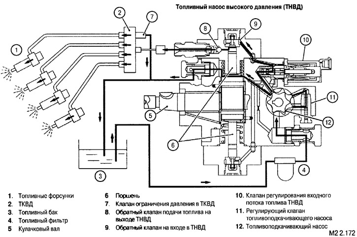
High pressure fuel pump (injection pump)
Fuel priming pump: delivers fuel from the fuel tank through the fuel filter to the injection pump,
Fuel priming pump control valve: Bypasses excess fuel into the return line if the pressure in the area between the priming pump and the injection pump fuel inlet flow control valve exceeds the set value.
Fuel Inlet Flow Control Valve Injection Pump: regulates the amount of fuel supplied (through injection pump) in the TKVD, according to the signals coming from the ECM.
Piston: having a constant stroke, creates a high pressure.
Check valve for fuel supply at the outlet of the injection pump: prevents the occurrence of a reverse flow of fuel from the fuel injection pump to the injection pump.
Injection pump inlet check valve: prevents back flow of fuel from the high pressure chamber to the low pressure fuel injection pump circuit.
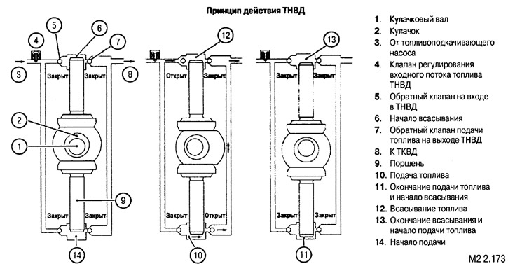
The principle of operation of the injection pump
The camshaft is driven by a toothed belt from the crankshaft and drives the fuel priming pump rotor as well as the cam pushing the high pressure pistons.
Cam driven pistons move in high pressure chambers. Depending on the position of the inlet and outlet valves and the direction of movement of the pistons in the chambers, fuel is alternately sucked in and injected into the supply line to the HPC.
Figure M2 2.173 shows the sequence of cycles of operation of each of the injection pump cylinders.
The ECM controls the correspondence between the current flowing through the winding of the fuel quantity control solenoid valve at the injection pump inlet and the amount of fuel injected into the fuel injection pump. The control is carried out using the data of the pressure sensor in the TKVD. Based on the results of comparing actual data with an array of control data, a regulatory action is generated in the ECM.
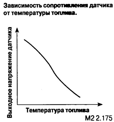
Fuel temperature sensor
The fuel temperature sensor is located on the injection pump. The temperature is determined by the change in the resistance of the sensor.
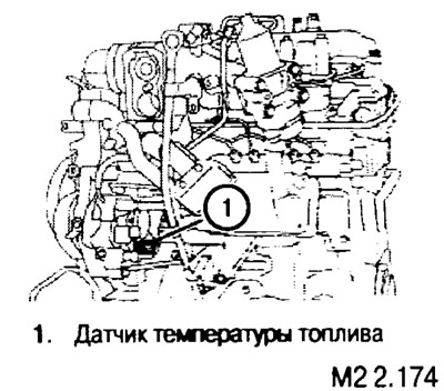
This sensor is a thermistor with a positive temperature coefficient of resistance.
Fuel inlet flow control valve
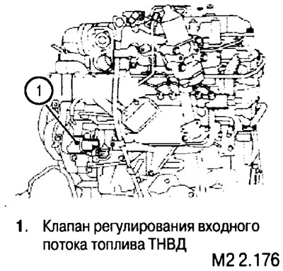
The degree of opening of the valve depends on the so-called duty cycle of the control signal pulses. In other words: the longer the impulse lasts within the repetition period, the greater the degree of opening of the valve.
The valve is located on the injection pump.
Fuel tank
The fuel tank consists of the following components:
- fuel tank capacity;
- receiving and measuring unit;
- fuel supply line;
- return fuel line.
The receiving and measuring unit includes the following components:
- fuel level sensor;
- fuel filter (immersed in a tank);
- fuel pipes.
Design features
In order to increase safety in the event of an accident, the fuel tank is located in front of the rear axle of the vehicle.
The design of the fuel tank provides for a valve that cuts off the fuel when the car is turned over.
In the manufacture of the fuel tank, for environmental reasons, materials containing lead or hexavalent chromium are not used.