
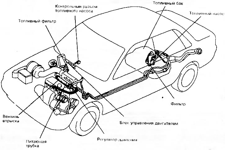
Typical arrangement of elements of the MPI fuel injection system
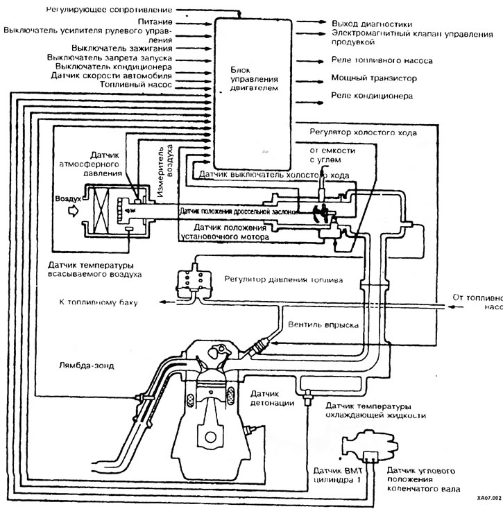
Scheme of the injection system
The operation of the MPI fuel injection system is carried out using several components and parts: the fuel pump, which is located in the fuel tank, pumps fuel from it and supplies it through the fuel filter through the distribution line to the injection valves (injectors). The injection valves are controlled by the control unit, which calculates the injection timing and the amount of fuel injected. When current flows through the solenoid winding, the needle of the injection valve is retracted and fuel is injected (when the current circuit is broken, the spring returns the needle, and the valve closes). The injection valves are controlled separately in the ignition sequence. The pressure regulator, located on the distribution line, maintains a constant pressure in the fuel system.
The intake air is cleaned in the air filter, in the housing of which there is an air mass meter that transmits information to the control unit. Pulse signals from other sensors also come there, for example, an atmospheric pressure meter or an intake air temperature sensor.
Cleaned air is supplied to the engine through the intake manifold.
Lambda probe (oxygen sensor) serves to measure the oxygen content in the exhaust gases and transmit information to the control unit in the form of voltage.
The throttle body contains a throttle valve that regulates the amount of air through the gas pedal. There is also an idle speed control mechanism in the throttle body that regulates the air supply bypassing the throttle. The position sensor of the adjusting motor and the idle speed switch are installed on the idle speed controller.